31
106309-03 - 4/19
Boiler Model
Nominal
Pipe
Diameter
Pipe Joint
Locking
Band Clamp
Combustion
Air
V
ent
Ipex Low
Profile
T
ermination
Adapter &
W
all Plate
Boiler
Adapter
Sidewall
T
ermination: UV
Resistant 90°
Elbow w/Screen
Roof
T
ermination:
(2) UV Resistant
90° Elbows
w/Screen
Boiler
Adapter
Sidewall * or Roof
T
ermination: UV
Resistant Straight
Pipe w/Screen
Flex
Chimney
Lining Kit
PHNTM399C (reduced dia.) PHNTM500C (reduced dia.)
3 in.
(80 mm)
2ZDLC3
2ZDCPVC4
with
2ZDR43
Elbow: 2ZDE387UV
Screen: 2ZDES3
Elbow: 2ZDE387UV
Screen: 2ZDES3
2ZD144 with
2ZDR43
Pipe: 2ZDP3(*) UV
Screen: 2ZDES3
2ZDFK325
or
2ZDFK335
N/A
PHNTM399C (standard dia.) PHNTM500C (standard dia.)
PHNTM600C (reduced dia. vent) PHNTM700C (reduced dia. vent) PHNTM800C (reduced dia. vent)
4 in.
(100 mm)
2ZDLC4
2ZDCPVC4
Elbow: 2ZDE487UV
Screen: 2ZDES4
Elbow: 2ZDE487UV
Screen: 2ZDES4
2ZD144;
PHNTM600C, PHNTM700C, & PHNTM800C:
2ZDCPVCCG6 with 2ZDR65 & 2ZDR54
Pipe: 2ZDP4(*)
Screen: 2ZDES4
2ZDFK425
or
2ZDFK435
N/A
PHNTM600C standard dia. vent) PHNTM700C standard dia. vent) PHNTM800C standard dia. vent)
6 in.
(150 mm)
2ZDLC6
2ZDCPVC4
Elbow: 2ZDE687
Screen: 2ZDES6
Elbow: 2ZDE687
Screen: 2ZDES6
2ZDCPVCCG6
Pipe: 2ZDP6(*)
Screen: 2ZDES6
N/A
N/A
* Note:
When using room air for combustion, use UV resistant 90° elbow or tee for sidewall vent termination. UV resistant 90° elbow part numbers: 2ZDE387UV (3 in.), 2ZDE487UV (4 in.), 2ZDE687UV (6 in.).
UV resistant tee part numbers: 2ZDTT3 (3 in.), 2ZDTT4 (4 in.), 2ZDTT6 (6 in.).
See Z-Flex Z-Dens literature for other required component part numbers such as straight pipe, elbows, firestops and vent supports.
(*) - Pipe Length
T
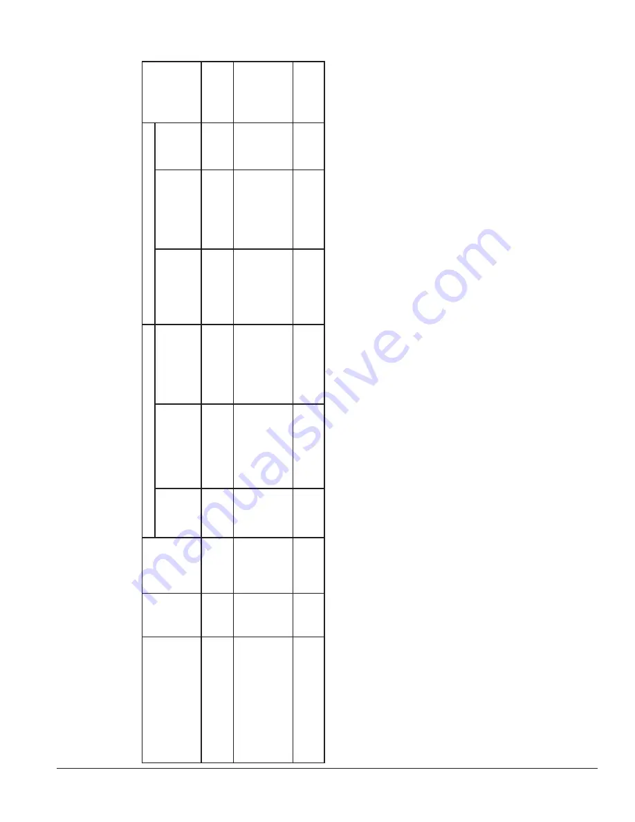
able 18: Listed Polypropylene Pipe, Fittings and T
erminations - Z-Flex Z-Dens
IV
. V
enting
B. CPVC/PVC V
enting (continued)
Summary of Contents for Phantom-X PHNTM399C
Page 49: ...49 106309 03 4 19 VI Water Piping and Trim continued Figure 28 Near Boiler Piping Heating Only...
Page 63: ...63 106309 03 4 19 VIII Electrical continued Figure 40 Ladder Diagram...
Page 64: ...64 106309 03 4 19 VIII Electrical continued Figure 41 Wiring Connections Diagram 2...
Page 73: ...73 106309 03 4 19 IX System Start up continued Figure 47 Operating Instructions...
Page 124: ...124 106309 03 4 19 XIII Service Parts continued...
Page 130: ...130 106309 03 4 19 XIII Service Parts continued...
Page 133: ...133 106309 03 4 19 XIII Service Parts continued 10A 10B 10C 10D 10G...
Page 139: ...139 106309 03 4 19...


