79
106309-03 - 4/19
IX. System Start-up
(continued)
Step
Parameter
Location
Parameter
Description
1
Adjust >>
System Setup
Outdoor Sensor Source
Select appropriate source: Not Installed, Wired or Wireless.
Warm Weather Shutdown
Enable/Disable
Selecting Enable will restrict boiler start during warm weather, but
only if an outdoor sensor is installed.
2
Adjust >>
Modulation Setup
Boiler Type
WARNING
Confirm correct boiler model is shown. Stop installation and contact
factory if incorrect boiler model is shown.
3
Adjust >>
Pump Setup
Boiler Circulator
Ensure pump parameter selections are correct for your application.
System Circulator
Domestic Circulator
4
Adjust >>
Contractor Setup
Contractor Name
Enter contact information. In the event of a fault, or the need
to adjust a setting, the display will direct the user to the entered
contact.
Contractor Address
Contractor Phone
5
Adjust >>
Central Heat
Setpoint
Ensure target space heating water temperature (Setpoint) is correct
for your type of radiation.
6
Adjust >>
Domestic Hot Water
Setpoint
Ensure target domestic hot water water temperature (Setpoint) is
correct.
DHW Modulation Sensor
If using DHW Sensor, select DHW Sensor.
7
Adjust >>
Outdoor Reset
Central Heat
Enable/Disable
If not using an outdoor sensor, select Disable.
8
Adjust >>
Sequencer Master
Sequencer Master
If boiler is the master boiler in a multiple boiler installation, select
Enable.
9
Adjust >>
Sequencer Slave
Boiler Address
If boiler is a slave boiler in a multiple boiler installation, assign a
unique boiler address.
10
Adjust>>
Energy
Management
Demand Source
If boiler is connected to an energy management system, select
Enable.
NOTE
: Disable boiler internal sequencer when connecting
to an energy management system.
11
Adjust>>
Energy
Management
Modulation Source
If using an external multiple boiler controller, set to 4-20 mA.
Central Heat Boiler
Setpoint Source
If an Energy Management System is sending a remote setpoint to
the boiler, set to 4-20 mA.
Table 41: Control Parameter Checklist
Summary of Contents for Phantom-X PHNTM399C
Page 49: ...49 106309 03 4 19 VI Water Piping and Trim continued Figure 28 Near Boiler Piping Heating Only...
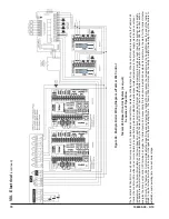
Page 63: ...63 106309 03 4 19 VIII Electrical continued Figure 40 Ladder Diagram...
Page 64: ...64 106309 03 4 19 VIII Electrical continued Figure 41 Wiring Connections Diagram 2...
Page 73: ...73 106309 03 4 19 IX System Start up continued Figure 47 Operating Instructions...
Page 124: ...124 106309 03 4 19 XIII Service Parts continued...
Page 130: ...130 106309 03 4 19 XIII Service Parts continued...
Page 133: ...133 106309 03 4 19 XIII Service Parts continued 10A 10B 10C 10D 10G...
Page 139: ...139 106309 03 4 19...


