119
106309-03 - 4/19
XII. Troubleshooting
(continued)
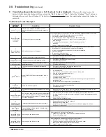
F. Troubleshooting problems where a Soft Lockout Code is displayed.
When a soft lockout occurs, the
boiler will shut down, the display will turn red and the “Help” button will “blink”. Select the “blinking” “Help” button to
determine the cause of the soft lockout. The boiler will automatically restart once the condition that caused the lockout is
corrected.
Soft Lockout Codes Displayed
Lockout
Number
Condition
Possible Cause
1
Anti Short Cycle
Minimum time between starts has not been
reached. Normal delay used to avoid excessive
cycles.
2
Boiler Recycling
Limits Open
(LCI OFF)
LCI safety limit input not energized.
Limit Control Input (LCI) is not ON. Refer to Limit String Status screen for list of limits.
• Auto Reset Ext. Limit device open or jumper not installed
• Low water condition (if using 24V LWCO)
• Flow switch open. Check boiler pump and flow switch wiring.
• Sump pressure switch open. Check for vent or combustion air
pipe blockage.
• Condensate float switch open. Check for condensate drain
blockage.
• Loose or defective limit string wiring
3
Burner Interlock
Open (ILK OFF)
ILK safety limit input not energized.
Lockout input (ILK) is not ON. Refer to Limit String Status screen for list of limits.
• Man Reset Ext. Limit device open or jumper not installed
• High or low gas pressure switch open or jumper not installed
• Thermal link open
• Burner door thermostat open
• Loose or defective limit string wiring
7
Return sensor fault Shorted or open return temperature sensor.
•
Shorted or mis-wired return sensor wiring.
•
Defective return sensor.
8
Supply sensor fault Shorted or open supply temperature sensor.
•
Shorted or mis-wired supply sensor wiring.
•
Defective supply sensor.
9
DHW sensor fault
Shorted or open Domestic Hot Water (DHW)
temperature sensor.
•
Shorted or mis-wired DHW sensor wiring.
•
Defective DHW sensor.
10
Stack sensor fault
Shorted or open flue gas (stack) temperature
sensor.
•
Shorted or mis-wired flue temperature sensor wiring.
•
Defective flue temperature sensor.
11
Ignition failure
Model PHNTM399C flame failure after 5 tries to
restart.
•
No gas pressure.
•
Gas pressure under minimum value shown on rating plate.
•
Gas line not completely purged of air.
•
Defective Electrode.
•
Loose burner ground connection.
•
Defective Ignition Cable.
•
Defective gas valve (check for 24 Vac at harness during trial for ignition before
replacing valve).
•
Air-fuel mixture out of adjustment - consult factory.
13
Flame rod
shorted to ground
Flame rod shorted to ground
•
Shorted or mis-wired flame rode wiring.
•
Defective flame rod.
14
D
T inlet/outlet high
Temperature rise between supply and return is too
high.
•
Inadequate boiler water flow. Verify that circulator is operating and that circulator
and piping are sized per Section VI of this manual.
15
Return temp higher
than supply
The Control is reading a return sensor temperature
higher than the supply sensor temperature. Condi
-
tion must be present for at least 75 seconds for this
error code to appear.
•
Flow through boiler reversed. Verify correct piping and circulator orientation.
•
No boiler water flow. Verify that system is purged of air and that appropriate valves
are open.
•
Sensor wiring reversed.
•
Supply or return sensor defective.
16
Supply temp has
risen too quickly
Supply water temperature has risen too quickly.
•
See possible causes for “Hard Lockout 4”.
•
Inadequate boiler water flow.
•
Verify that circulator is operating and that circulator and piping are sized per
Section VI of this manual.
17
Blower speed
not proved
Normal waiting for blower speed to match purge
and light-off setpoint.
27
Interrupted Airflow
Switch (IAS) ON
Air proving switch failed to open.
Air proving switch closed before Prepurge.
• Failed air proving switch. Check switch for proper operation.
• Short in limit string wiring
27
Interrupted Airflow
Switch (IAS) OFF
Air proving switch failed to close.
Air proving switch open during Prepurge or Drive Lightoff.
• Check for vent or combustion air pipe blockage.
• Confirm air proving switch hose connected to gas valve outlet
tapping and outlet tapping internal screw is open.
• Loose or defective limit string wiring
Summary of Contents for Phantom-X Series
Page 49: ...49 106309 03 4 19 VI Water Piping and Trim continued Figure 28 Near Boiler Piping Heating Only...
Page 63: ...63 106309 03 4 19 VIII Electrical continued Figure 40 Ladder Diagram...
Page 64: ...64 106309 03 4 19 VIII Electrical continued Figure 41 Wiring Connections Diagram 2...
Page 73: ...73 106309 03 4 19 IX System Start up continued Figure 47 Operating Instructions...
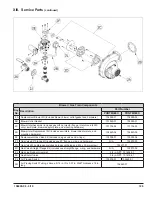
Page 124: ...124 106309 03 4 19 XIII Service Parts continued...
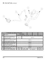
Page 130: ...130 106309 03 4 19 XIII Service Parts continued...
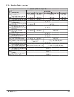
Page 133: ...133 106309 03 4 19 XIII Service Parts continued 10A 10B 10C 10D 10G...
Page 139: ...139 106309 03 4 19...


