13
106309-03 - 4/19
III. Pre-Installation and Boiler Mounting
G. General (continued)
H. Boiler Stacking
1. For installations with unusually high space heating
and/or domestic hot water heating loads, where
employing multiple boilers will offer the benefits of
greater operational efficiency, floor space savings
and boiler redundancy, boilers may be installed
stacked maximum one boiler on top of another.
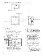
Refer to Table 6 “Phantom X Boiler Model Stacking
Combinations” for details.
Table 6: Phantom X Boiler Model Stacking
Combinations
Bottom
Boiler Model
Top Boiler Model
PHNTM399C
PHNTM399C
PHNTM500C
PHNTM399C or PHNTM500C
PHNTM600C
PHNTM399C, PHNTM500C, PHNTM600C
PHNTM700C
PHNTM399C, PHNTM500C, PHNTM 600C or
PHNTM700C
PHNTM800C
PHNTM399C. PHNTM500C, PHNTM600C,
PHNTM700C or PHNTM800C
2.
To field assemble individual Phantom X boilers into
a stackable configuration, use the steps below:
a. Position the bottom boiler first. Refer to Sections
II “Unpacking Boiler” and III “Pre-Installation
& Boiler Mounting” of the manual for details.
Always position higher input boiler model as
bottom boiler.
b. Each Phantom X boiler is factory packaged
with 2 stacking boiler attachment brackets (P/N
101679-01) and the bracket mounting hardware
[six (6) self-drilling hex washer head plated #8
x ½” long screws, P/N 80860743]. Locate and
remove the brackets and the hardware. The
stacking boiler attachment bracket has three
7/32” diameter holes punched in a triangular
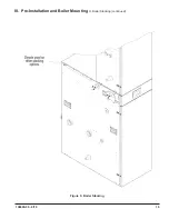
pattern. See Figure 5 “Boiler Stacking”.
c. Phantom X boiler left and right side panels have
a series of dimples at panel top and bottom.
These dimples are positioning dimples for
stacking boiler attachment bracket mounting
screws. Side panel bottom positioning dimples
are evenly spaced from boiler front and back,
while side panel top positioning dimples follow
specific pattern to compensate for Phantom X
boiler model variable depth.
d. Position the upper boiler on top of the bottom
boiler and align boiler front doors and sides flush
with each other.
• Place first stacking boiler attachment bracket
onto the upper boiler left side panel, at the
panel lower left corner and align bracket two
upper holes with corresponding side panel
lower dimples.
Figure 4: Clearances To Combustible and Non-combustible Material
Summary of Contents for Phantom-X Series
Page 49: ...49 106309 03 4 19 VI Water Piping and Trim continued Figure 28 Near Boiler Piping Heating Only...
Page 63: ...63 106309 03 4 19 VIII Electrical continued Figure 40 Ladder Diagram...
Page 64: ...64 106309 03 4 19 VIII Electrical continued Figure 41 Wiring Connections Diagram 2...
Page 73: ...73 106309 03 4 19 IX System Start up continued Figure 47 Operating Instructions...
Page 124: ...124 106309 03 4 19 XIII Service Parts continued...
Page 130: ...130 106309 03 4 19 XIII Service Parts continued...
Page 133: ...133 106309 03 4 19 XIII Service Parts continued 10A 10B 10C 10D 10G...
Page 139: ...139 106309 03 4 19...


