69
106309-03 - 4/19
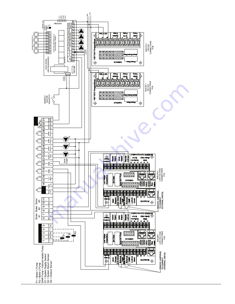
Tekmar 265 Based Control System (or equal)
Sequence of Operation
The
Tekmar 265 Control (or equal) can control up to three (3) boilers and an Indirect W
ater Heater
. When a call for heat is received by the
Tekmar 265 Control, the control
will fire either one or more boilers in either parallel or sequential firing mode to establish a required reset water temperature in the system supply main based on outdoor temperature.
The boilers will modulate based on an
Analog communication signal established between the
Tekmar 265 Control and each boiler
’s control.
The boiler(s) and
system supply water temperature will be reset together to maintain the input that is needed to the system. When a call for Indirect Hot W
ater is generated to the
Tekmar 265,
the control will de-energize the zone pump control (ZC terminal), energize the Indirect pump and modulate the boiler firing to establish a setpoint temperature in the main for the Indirect Heater using Priority
.
The
Tekmar 265 also controls each boiler
’s pump and a post purge of leftover temperature in the boilers will occur at the end of the call for Indirect
Hot W
ater
.
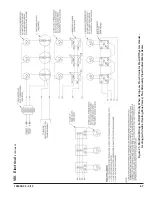
Figure 45: Multiple Boiler W
iring Diagram w/T
ekmar 265 Control
VIII. Electrical
(continued)
Summary of Contents for Phantom-X Series
Page 49: ...49 106309 03 4 19 VI Water Piping and Trim continued Figure 28 Near Boiler Piping Heating Only...
Page 63: ...63 106309 03 4 19 VIII Electrical continued Figure 40 Ladder Diagram...
Page 64: ...64 106309 03 4 19 VIII Electrical continued Figure 41 Wiring Connections Diagram 2...
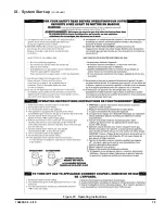
Page 73: ...73 106309 03 4 19 IX System Start up continued Figure 47 Operating Instructions...
Page 124: ...124 106309 03 4 19 XIII Service Parts continued...
Page 130: ...130 106309 03 4 19 XIII Service Parts continued...
Page 133: ...133 106309 03 4 19 XIII Service Parts continued 10A 10B 10C 10D 10G...
Page 139: ...139 106309 03 4 19...


