www.velocitydetection.com Doc: GLT-313-7-1 Issue: 001 Date: 28/10/2020
4) Special Conditions for Safe Use
Special Condition for safe Use as stated on the Type Examination
Certificate DEMKO 14 ATEX 4786493904X / CoC IECEx ULD
14.0004X:
End user shall adhere to the manufacturer’s installation and
instruction when performing housekeeping to avoid the potential
for hazardous electrostatic charger during cleaning, by using a damp
cloth.
The D2xC1 is not to be mounted with the horn facing upwards
The equipment shall only be used in end use with appropriately
certified cable entry devices and blanking plugs
4.1 Installation
The product must only be installed by suitably qualified personnel in
accordance with the latest issues of the relevant standards.
The installation of the units must also be in accordance with any
local codes that may apply and should only be carried out by a
competent electrical engineer who has the necessary training.
The equipment is not to be mounted with the horn facing upwards.
The equipment has not been assessed as a safety-related device (as
referred to by Directive 94/9/EC Annex II, clause 1.5).
The cable entry temperature may 70ºC / the cable
branching point may exceed 80ºC. Therefore suitable heat resisting
cables and cable glands must be used, with a rated service
temperature of at least 90ºC
To maintain the ingress protection rating and mode of protection,
the M20 x 1.5 cable entries must be fitted with suitably rated,
certified cable glands and/or suitably rated, certified blanking
devices during installation. If a high IP (Ingress Protection) rating is
required, then a suitable sealing washer must be fitted under the
cable gland. For use in explosive gas atmospheres a minimum
ingress protection rating of IP54 must be maintained. For use in
explosive dust atmospheres a minimum ingress protection rating of
IP64 must be maintained.
Only the front cover is to be used for access to the enclosure for
installation, service and maintenance. Once the product is opened,
the Type Rating cannot be maintained anymore unless a full
verification of the gasket material is done and there is no damage.
Connections are to be made into the terminal blocks using solid or
stranded wire, sizes 0.5-2.5mm2 / AWG 20-14. Wire insulation
needs to be stripped 6-7mm. Wires may be fitted securely with
crimped ferrules. Terminal screws need to be tightened down with a
tightening torque of 0.56 Nm / 5 Lb-in.
Internal earthing connections should be made to the internal earth
terminal on the PCBA. The earth conductor should be at least equal
in size and rating to the incoming power conductors. The internal
earth bonding wire connects the PCBA earth terminal to the internal
earth terminal in the enclosure back box.
External earthing connections should be made to the M5 earth stud,
using a ring crimp terminal to secure the earth conductor to the
earth stud. The external earth conductor should be at least 4mm
2
/
AWG 11 in size.
Check that the earth bonding wire between the two castings is
secure and the ‘O’ ring seal is in place and in good condition.
4.2 Maintenance, Overhaul and Repair
Maintenance, repair and overhaul of the equipment should only be
carried out by suitably qualified personnel in accordance with the
current relevant standards:
EN60079-19 / IEC60079-19 Explosive atmospheres - Equipment
repair, overhaul and reclamation
EN 60079-17/ IEC60079-17 Explosive atmospheres - Electrical
installations inspection and maintenance
Units must not be opened while an explosive atmosphere is present.
If opening the unit during maintenance operations a clean
environment must be maintained and any dust layer removed prior
to opening the unit.
Electrostatic charging hazard - Clean only with a damp cloth
D2xC1 Alarm Horn and Strobe should only be installed by trained
competent personnel.
5.1 Mounting
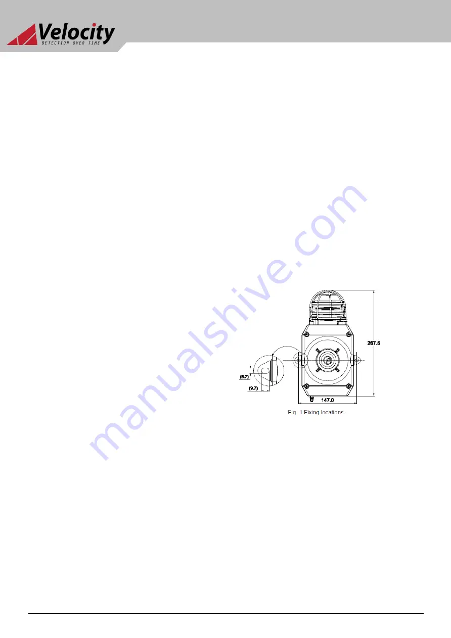
The D2xC1 Alarm Horn and Strobe may be secured to any flat
surface using the two 9.7 x 6.7mm, 147mm pitch fixing holes. The
enclosure provides IP66 protection and is suitable for installation in
exterior locations providing it is positioned so that water cannot
collect in the horn, and the cable entry is sealed.
5.2 Installation procedure
a)
Secure the D2xC1 Alarm Horn and Strobe to a flat surface
via the two 9.7 x 6.7mm, 147mm pitch fixing holes in the
mounting feet.
b)
Remove the front of the unit by unscrewing the four
captive cover screws and pulling the front away from the
enclosure.
c)
Fit an M20x1.5 suitably rated, certified cable gland or
conduit entry into the hole in the enclosure and connect
VL-D2xC1X05 Explosion Proof Horn Alarm & Strobe


