www.velocitydetection.com Doc: GLT-313-7-1 Issue: 001 Date: 28/10/2020
the field wiring to the appropriate alarm horn terminals as
shown in section 9 and fig 8 (DC) or section 8 fig 5 (AC) of
this manual. The power supply terminals are duplicated so
that horns may be connected in parallel and for DC units
only an end of line monitoring resistor may be fitted. If the
second M20x1.5 entry is not used a suitably rated,
certified stopping plug must always be fitted.
d)
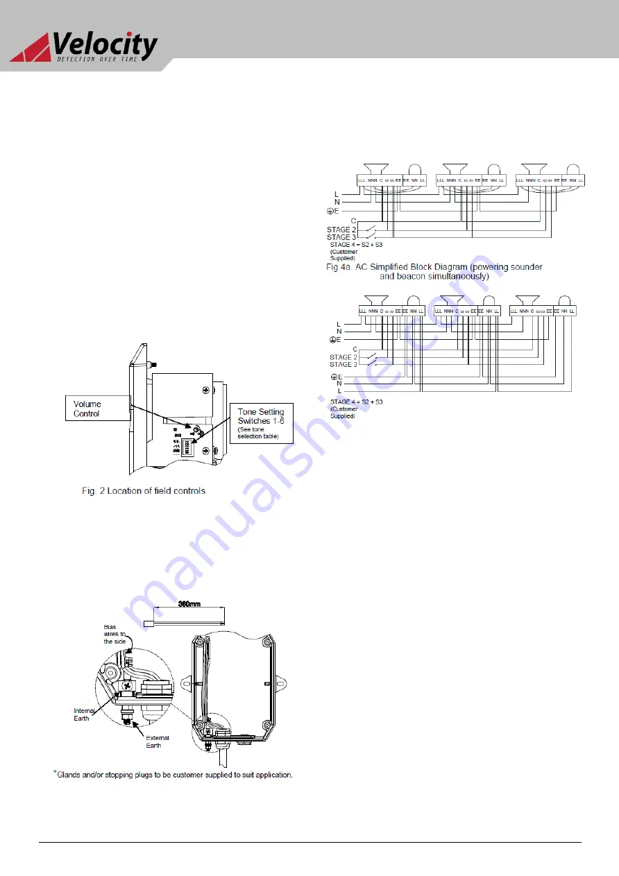
Select the required output tone by positioning the six
switches as shown in Table 1 and Fig 2.
e)
Adjust the internal volume control to provide the required
sound level.
f)
Check that the O-ring seal in the front cover is in good
condition and not damaged.
g)
Replace the front of the unit and tighten the four captive
cover screws.
6) Volume Control
The alarm horn output level of the D2xC1 unit can be set by
adjusting the volume control potentiometer (see Fig 2). For
maximum output, set the potentiometer fully clockwise.
7) Cable Routing and Tone Selection
7.1 Cable Routing
Due to the compact design of the D2x units, it is important that the
user strips the outer sheath of and biases any cables over the size of
1mm2 as shown below.
Fig 3. Cables are to be stripped and biased toward side of unit with
allocated spacing as shown.
8) AC Wiring
8.1 Wiring Diagram
8.2 Unit’s First
Stage Tones
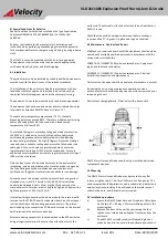
Stage one (S1) operation: Simply connect the supply voltage to the L
and N supply terminals, (see fig. 5). The Strobe is powered via
factory installed wires connected to the sounder. The wires
connecting the alarm horn and strobe can be removed if the user
wishes to power the strobe separately.
8.3 Second, Third and Fourth Stage Tone Selection
To select the second, third and fourth stage tones on the D2xS1 AC
alarm horns.
Stage two (S2) operation: Power L and N, link the common (C) and
S2 terminal.
Stage three (S3) operation: Power L and N, link the common (C) and
S3 terminals.
Stage four (S4) operation: Power L and N, link the common (C) and
both the S2 and S3 terminals.
Strobe will continue to flash during alarm horn S2, S3 & S4 stages.
Refer to Fig AC Terminals (over leaf)
VL-D2xC1X05 Explosion Proof Horn Alarm & Strobe


