background image

6

.

w w w . v e l o d y n e . c o m

Digital Drive User’s Manual

Figure 2: Digital Drive Rear Panel Connections

(1)

POWER 

Press the POWER switch to the ON position to activate the subwoofer. If

the unit is to be left unused for an extended period of time, move this switch to the
OFF position to prolong the life of the subwoofer.

(2)

117V~60Hz 15A 

Connect your detachable AC power plug to this male interface

connection. The detachable cord allows for easy replacement should the original
be damaged.

(3)

RS

-

232 IN 

Use this port to communicate with your computer (for software

updates), a touch panel remote control, or another upstream Digital Drive subwoofer.
See Appendix A for an explanation of the use of the serial port, available commands,
and their formats.

(4)

RS

-

232 OUT 

Use this port to communicate with a second “daisy

-

chained” Digital

Drive subwoofer. Also, the 12V trigger feature requires a 12V trigger signal (polarity
irrelevant) across pins 7 and 9 of this port.

(5)

EQ Video Output 

Used to display the video generated by the subwoofer.  S

-

Video or

composite connections are available (composite cable included).  NOTE: Only connect
to a single video output at a time.

Summary of Contents for Digital Drive

Page 1: ...Digital Drive U S E R S M A N U A L Featuring Software Version 2 0 ...

Page 2: ...Caution i w w w v e l o d y n e c o m Digital Drive User s Manual ...

Page 3: ...Attention ii w w w v e l o d y n e c o m Digital Drive User s Manual ...

Page 4: ...Vorsicht iii w w w v e l o d y n e c o m Digital Drive User s Manual ...

Page 5: ...Attenzione iv w w w v e l o d y n e c o m Digital Drive User s Manual ...

Page 6: ...onnections 9 A Word About Subwoofer Outputs 9 A Word About Interconnect Cables 10 A Word About Connecting More Than One Subwoofer 10 Subwoofer Setup OVERVIEW 12 ON SCREEN Setup 12 Onscreen Programming and Setup Step by Step 17 Restoring Defaults 37 About Room Equalization 42 Protection Circuitry 42 Care of Your Digital Drive Subwoofer 42 Troubleshooting and Service 43 Appendix A RS 232 Serial Over...

Page 7: ...ution when lifting or moving to avoid injury Remove all staples if used to seal the carton as they can scratch the cabinet Please save the carton and all packaging materials for future use Packing this unit in any other carton may result in severe damage when shipping Please take a moment to record the serial number and date location of purchase in the space provided on the warranty card for futur...

Page 8: ...plifier Tandem 3 voice coils Multi layer resin laminate cone High excursion rubber surround Gain compression anti clipping circuit to prevent over excursion and amp clipping Fixed 80Hz high pass crossover RCA output Balanced XLR input Line level RCA inputs and thruputs Speaker level inputs Variable volume control Frequency response of 20Hz 120Hz 3dB Detachable 6 foot AC power cord Four rubber 1 4 ...

Page 9: ...mote control allows you to set up adjust and reset your subwoofer when connected to a television or a video monitor You will also use your remote to activate preset listening values set the subwoofer s volume up or down mute the subwoofer or set a night operational mode Take care not to lose or misplace your remote control as adjustments to the subwoofer with the exception of volume control can on...

Page 10: ...ases and the light blinks out the volume level after you stop adjusting it For example for a volume of 34 you would see three long blinks followed by four shorter ones MUTE Mutes and unmutes the subwoofer TEST Used to toggle between the settings screen and the system response screen during setup EXIT To exit SETUP mode The unit will ask if you want to save settings before exiting SELECT To toggle ...

Page 11: ...vo subwoofer provides for a number of installation options Read all the installation information below in order to determine which installation option is best for your system Remember to perform all installation procedures with subwoofer unplugged until instructed to activate it SUBWOOFER CONTROLS AND POR TS The Velodyne Digital Drive subwoofer is set up configured and adjusted by the controls inp...

Page 12: ...nal be damaged 3 RS 232 IN Use this port to communicate with your computer for software updates a touch panel remote control or another upstream Digital Drive subwoofer See Appendix A for an explanation of the use of the serial port available commands and their formats 4 RS 232 OUT Use this port to communicate with a second daisy chained Digital Drive subwoofer Also the 12V trigger feature require...

Page 13: ...se of an 80Hz 6 dB octave slope high pass crossover 11 INPUT LFE This RCA input jack is for line level connection 12 REMOTE SENSOR This connection allows for hook up of the optional remote control receiver With the optional receiver plugged in you will be able to utilize all functions of the remote Place the infrared receiver within direct line of sight from your usual listening position 13 VOLUME...

Page 14: ...wer cable 2 Connect an LFE input cable from your receiver processor to the input jack For other hookup options see step 2 below 3 Power up the unit and ensure that it is receiving signal from your receiver i e playing bass 4 Connect the microphone in the accessory kit and place it in your favorite listening position Then press 3 2 1 on the remote 5 The unit should emit 25 sweep tones then restart ...

Page 15: ...ker wire into the correct binding post terminals or by removing the banana plug jack caps and inserting banana plug wire into the jacks NOTE Refrain from routing connections permanently at this time to accommodate subwoofer room placement as described below 3 Establish the line level connection optional Connect to a pre amplifier s main outputs and returning them to your amplifier inputs When inst...

Page 16: ...ounting stands Be sure to first remove the inner thread piece 3 8 16 before using 7 Connect the XLR microphone cable s female jack end with the male connector end of the microphone 8 Sheath the microphone pickup with the foam windscreen cover as a protection against dirt and airborne contaminants A Wor d About Inter connect Cables When installing your new Velodyne subwoofer using the line level co...

Page 17: ...e EQ on the master sub see setup steps 1 17 starting on page 17 Note the low pass crossover phase and polarity settings then save 3 Connect the video out of the slave subwoofer go to the settings screen establish the low pass crossover slope phase polarity and night mode settings from the master subwoofer then save settings Repeat for each slave subwoofer in your system 4 Connect the microphone to...

Page 18: ...utomatically saves settings and returns to normal operation Once the self EQ process starts pressing the RESET button can interrupt it Caution Self EQ resets all EQs for all presets to their default values DO NOT use the self EQ feature if you plan to adjust the DD subwoofer manually as described below ON SCREEN Setup This section describes adjusting the onscreen settings of your Digital Drive sub...

Page 19: ...gs such as preset volume etc they are shown on this screen You enter setup mode by pressing MENU and entering the code 12345 Upon successful entry of this code the system takes you to the EQ Setup screen as shown in Figure 4 HINT You do not need to press MENU to begin entering the setup code You can begin the 12345 sequence by pressing the number 1 on the remote ...

Page 20: ... graphic equalizer You use these settings to equalize your room The graphic equalizer features 8 bands each of which can be used at its current frequency or can be infinitely adjusted to the frequency and EQ you desire Each preset can have its own EQ settings By navigating the cursor to the NEXT field and pressing SELECT the following screen appears ...

Page 21: ...et can be individually adjusted if desired The presets are as follows they are also labeled on the remote 1 Action Adventure 2 Movies 3 Pop Rock 4 Jazz Classical 5 Custom off from the factory or flat 6 EQ Defeat All six presets contain the following fields Low Pass Crossover Frequency and Slope Adjust the upper limit of your subwoofer s frequency response Select a crossover setting in increments o...

Page 22: ...cut at the frequency specified in the contour frequency Again this has been preset at the factory but can be adjusted to taste Theater Music Indicator This setting affects the distortion limiting capabilities of the digital servo system and allows you to choose between a theatrical subwoofer a musical subwoofer or somewhere in between The scale is 1 for maximum theater least amount of servo gain a...

Page 23: ...ies to this level it is an ideal setting However some satellite speakers are only flat to 120Hz or even higher Remember that the higher the subwoofer is crossed over to match the satellite crossover settings the more likely it is to become directional that is you can tell where the bass is coming from Again consult your processor and speakers owner s manuals for more information 4 Select the sourc...

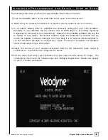
Page 24: ...18 w w w v e l o d y n e c o m Digital Drive User s Manual 6 Press MENU and enter 12345 to enter the EQ setup screen as follows ...

Page 25: ...19 w w w v e l o d y n e c o m Digital Drive User s Manual Upon pressing 5 you should see the following screen ...

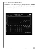
Page 26: ...processor until the DD test sweep a tone that sweeps from 20Hz up to 200Hz can be heard from your system s speakers Continue to raise the volume until the SYSTEM RESPONSE graph on your TV shows the response of your full range speakers the right hand portion of the graph at approximately 76 dB or a comfortable listening level This is shown below ...

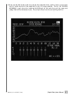
Page 27: ...he subwoofer then use the volume up and down keys to match the level of the subwoofer to your full range speakers That is the SYSTEM RESPONSE graph should be relatively flat although at this point there will be peaks and valleys that will be addressed next The screen should now look something like this ...

Page 28: ...ily be as low in distortion compared to a position away from the corner The worst location for a subwoofer is typically far away from any walls and close to the center of your room Avoid these locations when possible When using a pair of Velodyne subwoofers in stereo it is preferable to place each subwoofer by the satellite of the same channel If moving your satellites is an option they too can co...

Page 29: ...imum flexibility to make the most out of any subwoofer placement position 11 Now that the room location has been chosen turn off the subwoofer and the rest of your system permanently route the wiring and reconnect to your subwoofer 12 Reactivate the subwoofer and your system and ensure that the system works as before 13 Use the MENU button to get to the EQ setup screen after entering the 12345 cod...

Page 30: ...the low pass crossover begin by setting the frequency and slope to the same values as the crossover settings on your receiver processor for example many units have a large small satellite setting Again consult your receiver processor owner s manual for more information You will notice that changing these values cascades the values out to all the presets That is because once these values are set th...

Page 31: ...o m Digital Drive User s Manual TIP To see immediate feedback on the effects of your changes to the SYSTEM RESPONSE graph press the TEST button The following screen appears Press TEST again to return to the System Settings screen ...

Page 32: ...eivers processors supply a signal that is already crossed over i e just the bass frequencies If this is the case you will want to defeat the subwoofer s low pass crossover To defeat the low pass crossover press the SELECT key then the RESET key The following screen appears ...

Page 33: ...d to adjust the subsonic filter Do so only if there are anomalies in the very lowest frequencies that you cannot address using the normal EQ process as described below 17 Next adjust the phase and polarity settings Phase is in effect a short delay in the reproduction of the audio signal The polarity reverses the phase i e 180o shift Adjusting phase can change the dynamics of standing waves and fre...

Page 34: ...st the graphical EQs to eliminate peaks and valleys from the room response Use the right and left arrow keys to position the cursor over the EQ you wish to adjust If you see a peak in the response at say 25Hz this would be evident in the SYSTEM RESPONSE graph simply navigate the cursor to the EQ that corresponds to 25Hz and use the up or down arrow keys to slide the EQ up or down An example of thi...

Page 35: ...inue this process until the SYSTEM RESPONSE graph shows a 3 dB response across the bass frequencies that is up to about 120Hz Note that this does not necessarily mean a ruler flat response 3dB is typical for an optimized response curve An equalized room is shown below ...

Page 36: ...d the unit automatically resets all EQs to their original frequencies and Q settings but retains any level changes you may have made The AUTO EQ proceeds until you either save settings press SELECT to return to manual EQ move the cursor off the AUTO EQ field in which case the field automatically reverts to MANUAL or twenty five sweeps have occurred ...

Page 37: ...alizer to achieve room equalization If you do not wish to use the parametric EQ feature skip to step 24 21 To use the parametric EQ feature position the cursor over the EQ and press the SELECT button The values for that particular EQ appear on the right hand side of the screen The following screen is shown ...

Page 38: ...d the SET and SET keys to change the Q value Use the UP and DOWN arrow keys to adjust the level of the EQ as before A selected EQ that has been moved with its level raised and Q adjusted is shown below 23 To unselect the EQ press SELECT again then use the right and left arrow keys to position the cursor on another EQ if desired and repeat step 22 until the room is equalized ...

Page 39: ...gs Setup screen by positioning the cursor over the NEXT field on the EQ setup screen and pressing SELECT and review modify the presets This step is required ONLY if you wish to customize the presets Before doing this LOCK the Setup column by positioning the cursor over the LOCK screen and pressing SELECT This screen is shown below ...

Page 40: ...p that 30 was a good setup volume for the subwoofer then if you increased the volume for preset one to 40 the 40 volume would be invoked when preset one were selected for listening If the system volume is changed using the VOL or VOL keys on the remote the preset volume is adjusted in lock step with the system volume Crossover subsonic filter phase and polarity settings Normally these will not cha...

Page 41: ...ck making an overall louder and more impressive sub for explosions and other theatrical content The scale is 1 for theater least amount of servo gain and 8 for music most amount of servo gain EQ curves Each preset can have its own unique set of EQ settings You can select which preset you want to EQ by either positioning the cursor on a preset column on the settings screen then pressing TEST or by ...

Page 42: ...ound flat especially at lower levels you may need to increase the subwoofer volume in relation to the satellite speakers An increase of about 5 8 dB is usually adequate There are two methods to accomplish this 1 Raise the internal volume control for the subwoofer in your surround receiver or processor or 2 Raise the volume of your Digital Drive subwoofer after you have finished your room equalizat...

Page 43: ...ht tick in your main speakers This is normal behavior NOTE The Digital Drive subwoofer stores all of its settings in internal Flash memory This memory persists even if the woofer is turned off loses power or undergoes a programming update so you need not worry about losing your customized settings There is a feature in Digital Drive that allows you to restore the factory defaults On the Main Scree...

Page 44: ...o raise or lower the subwoofer s volume use the light and night buttons to control the logo light and night mode respectively and use the mute button to mute the subwoofer These settings are shown on the introductory screen as follows NOTE If you change the volume on your DD subwoofer but later wish to return to the volume you established during setup that is as of your last save press the RESET b...

Page 45: ...untime Inactive Modes The following screens show other runtime messages indicating that the subwoofer is inactive The screen below shows the message displayed when the auto off feature has engaged that is the subwoofer has not had any input signal for 15 minutes ...

Page 46: ...y n e c o m Digital Drive User s Manual The following screen is displayed when the POWER button is depressed powering down the subwoofer Note that in this mode the POWER button must be pressed again to reactivate the unit ...

Page 47: ...41 w w w v e l o d y n e c o m Digital Drive User s Manual The following screen is shown when the unit is waiting for a 12 volt trigger to activate ...

Page 48: ...eatest reliability The unit is protected against 1 Overdriving the speaker or amplifier 2 Overheating the amplifier 3 Excessive drop in power line voltage The first type of protection circuitry that prevents overdriving of the speaker or amplifier operates constantly without being audible under most situations In some extreme situations sustained high output levels such as pro sound usage the unit...

Page 49: ...ily The following conditions require service by a qualified technician 1 The power cord has become damaged 2 The unit does not appear to operate normally or exhibits a marked change in performance 3 The unit has been exposed to water 4 Some part of the cabinet or circuitry is physically damaged Software Updates At the heart of Digital Drive functionality is the customized software From time to tim...

Page 50: ...600 Data Bits 7 Parity None Stop Bits 1 DD IN and OUT Por t Pin Configuration DD serial ports use a standard configuration that allows direct connection to a PC via a FEMALE to MALE serial cable It uses only 3 pins Transmit Receive Ground The pin configurations are IN Pin 2 Transmit Pin 3 Receive Pin 5 Ground OUT Pin 2 Receive Pin 3 Transmit Pin 5 Ground Runtime Command Format Byte Number Byte Des...

Page 51: ...cated PS 5 6 PS3 PS4 preset or requests PS5 PS6 the current preset PS Logo Light LTn 0 Light Off LT0 Turns the Logo Light Control LT 1 Light On LT1 on or off or requests LT light state Night Mode NMn 0 Night NM0 Activates Deactivates Control NM Mode Off NM1 Night Mode or 1 Night NM requests light Mode On mode state Mute Control MUn 0 Mute Off MU1 Mutes Unmutes the MU 1 Mute On MU woofer or request...

Page 52: ... unit saves and resets Restore defaults 8 9 0 Restores defaults and resets the subwoofer Switch to DOWN ARROW The unit restarts in PAL SECAM 4 times followed PAL SECAM video mode video by RESET TO restore NTSC mode restore defaults Display serial number UP ARROW 4 times Shows the serial number then SELECT of the unit at the top of the screen Restore last saved RESET If volume is changed volume res...

Page 53: ...Q it does not affect phase crossovers or other settings Individual EQs per preset Each preset can have its own independent EQ setup or all can be affected through the SETUP selection Also EQ curves reflect the effect of ALL settings for each preset e g crossovers phase etc Previously these settings only reflected the SETUP values Defeatable Low Pass Crossover The low pass crossover can be complete...

Page 54: ...e screen when TEST key is graph screen but the only function was to press pressed on settings screen TEST again to return to the settings screen Now the graph screen is fully functional and pressing test again puts the user at the field where they left off on the settings screen Light blink scheme for When the volume up or down buttons are pressed volume level the Velodyne light will blink faster ...

Page 55: ... to the Sub Out connector of the THX Pre Amp Receiver Also set the DD 15 DD 18 to the THX Preset 5 set the system response of the subwoofer as per the owners manual and then calibrate the THX Pre Amp Receiver This ensures that the bass management and calibrated levels are optimized for your system As this is a new THX Ultra2 subwoofer if your Pre Amp Receiver is THX Ultra2 Certified you may use th...

Page 56: ...ty are made to any component of the system by anyone other than a VELODYNE factory authorized service representative 3 VELODYNE is not responsible for damage caused by accidents abuse misuse natural or personal disaster or unauthorized modification The VELODYNE products are not intended for professional or commercial use and VELODYNE is not responsible for damage resulting from such use 4 The VELO...

Page 57: ...odyne Acoustics Inc 345 Digital Drive Morgan Hill CA 95037 408 465 2800 voice 408 779 9227 fax 408 779 9208 service fax www velodyne com Service E mail service velodyne com Product E mail help velodyne com Technical E mail techhelp velodyne com 63 DD RevF 11MAY05 ...

Reviews: