background image

[ 12 ]

HDL-32E User’s Manual

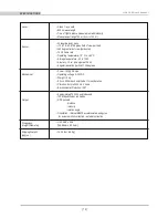
sPecifications

Laser:

Sensor:

Mechanical:

Output:

Dimensions:
(Height//Diameter)

Shipping Weight:
(approx.)

• Class 1 - eye safe  
• 905 nm wavelength 
• Time of flight distance measurement with intensity
• Measurement range 100 m (5 cm to 100 m)

• 32 laser/detector pairs  
• +10.67 to -30.67 degrees field of view (vertical)
• 360 degree field of view (horizontal)  
• 10 Hz frame rate 
• Operating temperature -10° C to +60° C
• Storage temperature - 40 to 105 C
• Accuracy: <2 cm (one sigma at 25 m)
• Angular resolution (vertical) 1.33 degrees

• Power: 12V @ 2 Amps
• Operating voltage: 9-32 VDC
• Weight: <2 kg
• Shock: 500 m/sec2 amplitude, 11 msec duration
• Vibration: 5 Hz to 2000 Hz, 3 Grms
• Environmental Protection: IP67

• Approximately 700,000 points/second 
• 100 Mbps Ethernet connection
• UDP packets

- distance
- intensity
- rotation angle

• Orientation - internal MEMS accelerometers and gyros  

for six-axis motion correction - external correction

• Unit: 5.68” x 3.36”

[149.86mm x 85.3mm]

• 14.35 lbs [ 6.5 Kg]

Summary of Contents for HDL-32E

Page 1: ...HDL 32E High Definition LiDAR Sensor U S E R S M A N U A L A N D P R O G R A M M I N G G U I D E ...

Page 2: ...S Time Stamping Time Stamping Accuracy Rates Laser Timing Laser Firing Sequence T R O U B L E S H O O T I N G S E R V I C E A N D M A I N T E N A N C E S P E C I F I C AT I O N S A P P E N D I X A Digital Sensor Recorder DSR A P P E N D I X B HDL 32E Sample Data Packets A P P E N D I X C Coordinate Calculation Algorithm Sample Code A P P E N D I X D Calibration and Orientation A P P E N D I X E Et...

Page 3: ...ser to the presence of important operating and maintenance servicing instructions in the literature accompanying the product 1 Read Instructions All safety and operating instructions should be read before the product is operated 2 Retain Instructions The safety and operating instructions should be retained for future reference 3 Heed Warnings All warnings on the product and in the operating instru...

Page 4: ... imaging This manual describes how to set up and operate the HDL 32E covers installation and wiring addresses output packet construction and interpretation along with GPS installation notes This manual is undergoing constant revision and improvement check www velodynelidar com for updates 1 HDL 32E User s Manual introduction ...

Page 5: ...waveform analysis provide high accuracy extended distance sensing and intensity data The HDL 32E uses a direct drive motor system employing no belts or chains in the drive train to improve reliability and reduce maintenance The unit provides A 360 horizontal field of view FOV A 41 3 vertical FOV Usable returns up to 100 meters Figure 1 Overview of the LiDAR HDL 32E 3D Imaging System 2 HDL 32E User...

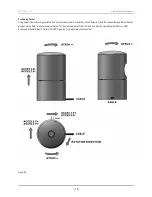
Page 6: ...ately 3 meter cable terminated at an interface box Desktop AC DC power adapter AC cord 4 5 meter Ethernet cable Garmin GPS 18LV GPS receiver with 5 meter cable CD with User manual Check www velodynelidar com for updates Calibration file db xml DSR Viewer software Mount Base The sensor base provides mounting holes on the base The sensor can be mounted at any angle from 0 to 360 with respect to the ...

Page 7: ...is designed to withstand standard automotive G forces 500 m sec2 amplitude 11 msec duration shock and 3 Grms 5 Hz to 2000 Hz vibration Wiring The HDL 32E comes with an integral cable that is terminated at an interface box The cable is approximately 3 meters 10 in length The interface box provides jacks for Ethernet power and GPS Power The 2 1 mm barrel plug jack fits the AC DC power adapter includ...

Page 8: ...tion distance and intensity data 4 Apply the calibration factors to the data 5 Plot or store the data as needed Each of these steps is described in detail below 1 Establish communication with the HDL 32E The HDL 32E outputs two separate broadcast UDP packets By using a network monitoring tool such as Wireshark you can capture and observe the packets as they are generated by the unit HDL 32 MAC ID ...

Page 9: ...e on packet construction see Appendix B 4 Apply the calibration factors to the data Each of the HDL 32E s lasers is fixed with respect to vertical angle For each data point issued by the sensor vertical correction factors must be applied to determine the point s location in 3D space referred to by the return note The minimum return distance for the HDL 32E is approximately 5 cm Ignore returns clos...

Page 10: ... a connector that plugs into the HDL 32E interface box and pre programmed to output the correct GPS record and sync pulse GPS Receiver Option 2 Customer s GPS Receiver Under this option the customer must configure their GPS device to issue a once a second synchronization pulse typically output over a dedicated wire and issue a once a second GPRMC NMEA record No other output can be accepted from th...

Page 11: ...es below show the GPS receiver included with the HDL 32E GPS EQUIPMENT GPS Interface Box Front Back View Ethernet Cable Power Adapter AC Cord HDL 32E Garmin GPS 18LV GPS Receiver Interface Box Interface Box Top View Interface Box Front View ...

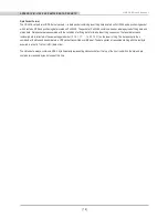
Page 12: ...s 3 If the GPS is then disconnected the HDL 32E will continue to run on its own clock and be subject to a drift of approximately 5 seconds per day Laser Timing If the GPS timestamp feature is employed it may be useful to determine the exact firing time for each laser so as to properly time align the HDL 32E point cloud with other data sources The Ethernet packet is assembled in real time therefore...

Page 13: ... the stack or DSR 15 is set at a 0 vertical angle This laser can be used as a reference to calibrate pitch and yaw of the sensor relative to the vehicle 10 HDL 32E User s Manual usaGe Firing order DSR Vertical angle 1 0 30 67 2 1 9 33 3 2 29 33 4 3 8 00 5 4 28 00 6 5 6 66 7 6 26 66 8 7 5 33 9 8 25 33 10 9 4 00 11 10 24 00 12 11 2 67 13 12 22 67 14 13 1 33 15 14 21 33 16 15 0 00 17 16 20 00 18 17 1...

Page 14: ... one amp Inspect the fuse in the interface module Replace if necessary Unit spins but no data Verify Ethernet wiring Verify packet output using another application e g Ethereal Wireshark Verify network settings Set a static IP address in network settings 192 168 3 255 There are no user service or maintenance requirements or procedures for the Velodyne HDL 32E For service or maintenance please cont...

Page 15: ...e Operating temperature 10 C to 60 C Storage temperature 40 to 105 C Accuracy 2 cm one sigma at 25 m Angular resolution vertical 1 33 degrees Power 12V 2 Amps Operating voltage 9 32 VDC Weight 2 kg Shock 500 m sec2 amplitude 11 msec duration Vibration 5 Hz to 2000 Hz 3 Grms Environmental Protection IP67 Approximately 700 000 points second 100 Mbps Ethernet connection UDP packets distance intensity...

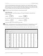
Page 16: ...mented properly the image viewable from the DSR is calibrated to provide an accurate visual representation of the environment in which the sensor is being used Also use these calibration factors and equations in any program using the data generated by the unit Live Playback For live playback first secure and power up the HDL 32E sensor so that it is spinning Connect the RJ45 Ethernet connector to ...

Page 17: ...mand to open a previously captured pcap file for playback The DSR playback controls are similar to any DVD VCR control features PLAY button PAUSE button Press the Play button to render the file The Play button will alternate to Pause when in playback mode FORWARD button REVERSE button Use the Forward and Reverse buttons to change the direction of playback note The X Y Z and distance figures at the...

Page 18: ...e CW Shift R Rotate CCW Z Shift F Forward B Back X Shift L Left H Right Y Shift U Up D Down Aux Functions Ctrl Z Y P R F B L H U D Direction Fine Movement Alt Z Y P R F B L H U D Direction Very Fine Movement DSR Mouse Controls Rotational Left Button Move Slide Right Button Move Zoom Scroll forward Zoom In Scroll backward Zoom Out 15 HDL 32E User s Manual aPPendix a ...

Page 19: ... sequences The laser distance and instensity data is collected in the same staggered order 0 16 1 17 14 30 15 31 as the laser is firing The data packet is then combined with status and header data in a UDP packet transmitted over Ethernet The data packet is transmitted starting with the last byte acquired in a last in first out LIFO data order The status data always contains a GPS 4 byte timestamp...

Page 20: ...Figure B1 17 HDL 32E User s Manual aPPendix B Blank Blank Start identifier OxEEFF 2 mm increments 0 no return within 100 m User Datagram Protocol UDP Ethernet Data Packet Format HDL 32E Port 2368 ...

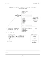
Page 21: ...Figure B2 the positioning ethernet Packet provides motion data rotational and acceleration for the stationary base of the HDL 32E unit See the User Datagram Protocol UDP Positioning Ethernet Packet Format HDL 32E Figure B3 for interpretation of data output Figure B2 18 HDL 32E User s Manual aPPendix B I 0 degrees ...

Page 22: ...Figure B3 19 HDL 32E User s Manual aPPendix B ...

Page 23: ... bd 9c 91 2442968444 919cbd7c hex usec 2442 9sec Time stamp from the head of the hour in usec NMEA Sentence GPRMC 214042 A 3708 3087 N 12139 5146W 000 0 000 0 160311 014 8 E A 0C 20 HDL 32E User s Manual aPPendix B ...

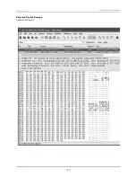
Page 24: ...Ethernet Packet Example Captured via Wireshark 21 HDL 32E User s Manual aPPendix B ...

Page 25: ... db getDistLSB float data points idx distance Get measured distance distance1 float cosVertAngle cal getCosVertCorrection float sinVertAngle cal getSinVertCorrection float cosRotAngle rotCosTable data position float sinRotAngle rotSinTable data position float xyDistance distance cosVertAngle Convert to X Y plane coords idx setX xyDistance sinRotAngle pos getX VLS_DIM_SCALE Calculate X coordinate c...

Page 26: ...libration of either the deflection horizontal or rotational angle is necessary both the horizontal angle and rotational laser angles are always zero The vertical angle of each laser is described in the XML file supplied with each unit and as listed above This is the only calibration parameter necessary to plot points in 3D space so for the HDL 32E all db xml calibration files are identical and con...

Page 27: ...om the packet timestamp microseconds from the top of the hour to arrive at actual laser firing time Rotary encoder value is read at the beginning of packet creatione at actual laser firing time Timestamp is recorded and written at end of packet creation Formula to determine timing is 542 592 Packet Offset 100 46 08 Dsr 1 152 ...

Page 28: ...9208 service fax www velodynelidar com Service Email lidarservice velodyne com Sales Email lidar velodyne com All Velodyne products are made in the U S A Specifications subject to change without notice Other trademarks or registered trademarks are property of their respective owner 63 9113 Rev A APR2011 ...

Reviews: