HDL-64E S3
High Definition LiDAR Sensor
Page 11
Velodyne LiDAR, Inc.
©
2019
63-HDL64ES3 REV K
4. Apply the calibration factors to the data.
Each of the sensors’s lasers is fixed with respect to vertical angle and offset to the rotational
index data provided in each packet. For each data point issued by the sensor, rotational and
horizontal correction factors must be applied to determine the point’s location in 3D space
referred to by the return. Intensity and distance offsets must also be applied. Each sensor comes
from Velodyne’s factory calibrated using a dual-point calibration methodology, explained further in
Appendix F.
NOTE:
The minimum return distance for the sensor is approximately 3 feet (0.9 meters). Ignore
returns closer than this.
NOTE:
A file on the CD called “HDL Source Example” shows the calculations using the above
correction factors. This DSR uses this code to determine 3D locations of sensor data points.
5. Plot or store the data as needed.
For DSR, the point-cloud data, once determined, is plotted onscreen. The source to do this can
be found on the CD and is entitled “HDL Plotting Example.” DSR uses OpenGL to do its plotting.
You may also want to store the data. If so, it may be useful to timestamp the data so it can be
referenced and coordinated with other sensor data later. The sensor has the capability to
synchronize its data with GPS precision time. For more in this capability, see the
External GPS
Time Synchronization
section.
Summary of Contents for HDL-64E S3
Page 1: ...USER S MANUAL AND PROGRAMMING GUIDE HDL 64E S3 High Definition LiDAR Sensor ...
Page 40: ...HDL 64E S3 High Definition LiDAR Sensor Page 40 Velodyne LiDAR Inc 2019 63 HDL64ES3 REV K ...
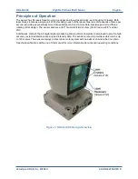
Page 41: ...HDL 64E S3 High Definition LiDAR Sensor Page 41 Velodyne LiDAR Inc 2019 63 HDL64ES3 REV K ...
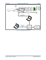
Page 42: ...HDL 64E S3 High Definition LiDAR Sensor Page 42 Velodyne LiDAR Inc 2019 63 HDL64ES3 REV K ...

