background image

HDL

-64E

U S E R ’ S

M A N U A L

H i g h   D e f i n i t i o n   L i d a r

S e n s o r

Summary of Contents for HDL-64E

Page 1: ...HDL 64E U S E R S M A N U A L High Definition Lidar Sensor ...

Page 2: ...Caution i w w w v e l o d y n e c o m HDL 64E User s Manual INVISIBLE LASER RADIATION DO NOT VIEW DIRECTLY WITH OPTICAL INSTRUMENTS CLASS 1M LASER PRODUCT ...

Page 3: ...tallation Overview 3 Mounting 3 Wiring 6 Usage 6 Data Packet Construction 6 Correction Angles 7 Controlling the Spin Rate 8 Firmware Update 8 Troubleshooting 9 Service and Maintenance 9 Specifications 10 Appendix A Connector Wiring Diagram 11 Appendix B Angular Resolution 12 Appendix C Digital Sensor Recorder DSR 13 ...

Page 4: ...about the surrounding environment than previously possible This guide first covers installation and wiring then addresses output packet construction and interpretation and finally discusses the serial interface to the unit and software updates This manual is undergoing constant revision and improvement check www velodyne com lidar for updates Each shipment contains HDL 64E sensor Wiring harness CD...

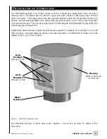
Page 5: ... cloud than conventional designs The unit inherently delivers a 360 degree horizontal field of view FOV and a 26 8 degree vertical FOV Additionally state of the art signal processing and waveform analysis are employed to provide high accuracy extended distance sensing and intensity data The HDL 64E is rated to provide usable returns up to 120 meters Figure 1 HDL 64E design overview The HDL 64E emp...

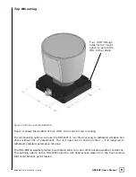
Page 6: ... mounting options Figure 3 for side side mounting and Figure 4 for top mounting instructions Figure 2 Front and back HDL mounting illustration See Figure 2 This figure shows the HDL 64E s base plate screw locations with threaded inserts for standard M8 hardware Ins tallation Ov ervie w Four M8 1 25 x 12mm deep mounting points Four per side for a total of 16 Mounting Base ...

Page 7: ...4 w w w v e l o d y n e c o m HDL 64E User s Manual Side Mounting Figure 3 Side side HDL mounting illustration Mounting Base ...

Page 8: ...to withstand vibration and shock without risk of detachment The unit need not be shock proofed it is designed to withstand standard automotive G forces The HDL 64E is weatherproofed to withstand wind rain and other adverse weather conditions The spinning nature of the HDL 64E helps the unit shed excess water from the front window that could hamper performance Four 406 through holes for top mount o...

Page 9: ...data followed by six bytes at the end of each packet that contains a spin counter and firmware version information Each packet can be for either the upper or lower laser banks called laser blocks each bank contains 32 lasers The packet format is as follows 2 bytes of header info This header indicates whether the packet is for the upper block or the lower block The upper block will have a header of...

Page 10: ...ret the packet data rotCorrection This parameter is the rotational correction angle for each laser as viewed from the back of the unit Positive factors rotate to the left and negative values rotate to the right vertCorrection This parameter is the vertical correction angle for each laser as viewed from the back of the unit Positive values have the laser pointing up and negative values have the las...

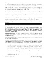
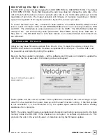
Page 11: ...L 64E has no echo back feature so no serial data will be returned from the HDL 64E Velodyne may issue firmware updates from time to time To apply the update connect the DB9 RS 232 cable to a standard Windows compatible PC s serial port The HDL 64E must be powered up and spinning during the update Execute the file supplied by Velodyne all the software and firmware is included to update the unit Onc...

Page 12: ...sary Unit spins but no data Verify Ethernet wiring Verify packet output from another source e g Ethereal Wireshark No serial communication Verify RS 232 cable connection Unit must be active and spinning for RS 232 update It may take several tries for the update to be effective There are no user service or maintenance requirements or procedures for the Velodyne HDL 64E For service or maintenance pl...

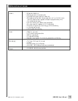
Page 13: ...ately 0 4 5 cm distance accuracy 5 15 Hz rotation rate update user selectable 50 meter range for pavement 0 10 reflectivity 120 meter range for cars and foliage 0 80 reflectivity 1M points per second 0 05 milliseconds latency Class Im eye safe 4 x 16 laser block assemblies 905 nm wavelength 10 nanosecond pulse Adaptive power system for minimizing saturation and blinding 12V input 16V max 4 amps 29...

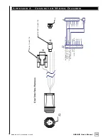
Page 14: ...al J1 J2 D E I J F G H A B C KEY PIN 1 SERIAL CONNECTOR ETHERNET CONNECTOR P1 P1 3 J2 8 7 5 4 6 2 1 J1 EHTERNET OUT EHTERNET IN EHTERNET OUT EHTERNET IN GND 12 16VDC P5 P3 N C N C N C N C N C N C N C N C N C N C RED BLK YEL SHIELD RED B C F G I J D A H CENTER CON E User Interface Harness ...

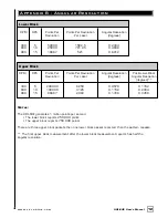
Page 15: ...r Resolution Post Lower Block Revolution Per Laser degrees Angular Resolution degrees 300 5 200000 6250 0 0576 0 1152 600 10 100000 3125 0 1152 0 2304 900 15 66667 2083 0 1728 0 3456 Notes The HDL 64E generates 1 million points per second The lower block reports 250 000 points The upper block reports 750 000 points There are three upper block packets then one lower block packet reported then the p...

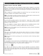
Page 16: ...is complete follow the Utilizing the db xml calibration data file in DSR instructions in the next section to calibrate the DSR viewer to your new sensor Note failure to use the calibration db xml file supplied with your sensor will result in sub optimal point cloud rendering in DSR Using DSR DSR gives the user the ability to view point cloud data in real time or to create a recording of such data ...

Page 17: ... button again to discontinue the capture One can string multiple recordings together on the same file by performing the Record function repeatedly A new file name will not be requested until after the session has been aborted Note An Ethernet capture utility such as Wireshark can also be used as a pcap capture utility Playback of Recor ded files Use the File Open command to open a previously captu...

Page 18: ... which the sensor is being applied This data should also be used in any other program using the data generated by the HDL 64E To integrate the db XML file into the DSR pr ogram follow these steps 1 Provided that DSR has been installed on the host computer using the default settings follow this path c program files Digital Sensor Recorder 2 Cut and paste the existing db XML file to another location...

Page 19: ...16 w w w v e l o d y n e c o m HDL 64E User s Manual Figure 6 Calibration values as seen in DSR File Properties ...

Page 20: ...CW Shift P Rotate CCW Y axis rotation R Rotate CW Shift R Rotate CCW Z Shift F Forward B Back X Shift L Left H Right Y Shift U Up D Down Aux Functions Ctrl Z Y P R F B L H U D Direction Fine Movement Alt Z Y P R F B L H U D Direction Very Fine Movement DSR Mouse Contr ols Rotational Left Button Move Slide Right Button Move Zoom Scroll forward Zoom In Scroll backward Zoom Out ...

Page 21: ...ill CA 95037 408 465 2800 voice 408 779 9227 fax 408 779 9208 service fax www velodyne com Service E mail service velodyne com Product E mail help velodyne com Technical E mail techhelp velodyne com Sales E mail lidar velodyne com 63 HDL 64E Rev D MAR08 Trademarks are property of their respective owners ...

Reviews: