background image

13

MicroVee X Series

User’s Manual

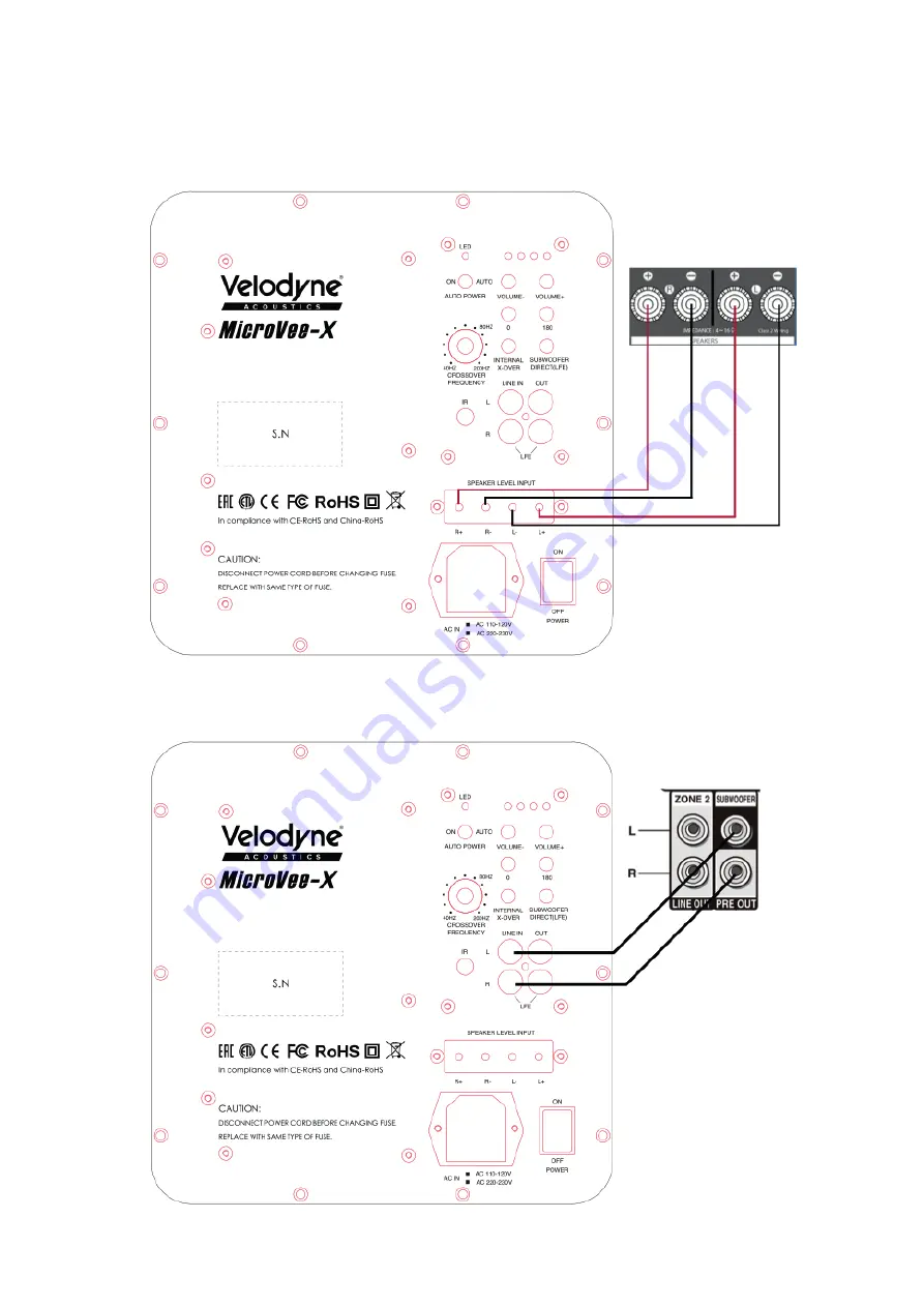
Figure 3b: Speaker-Level Subwoofer Connection Diagram 

Figure 3c: Stereo RCA/ Pre out Subwoofer Connection Diagram

Summary of Contents for MicroVee X Series

Page 1: ...USER S MANUAL MicroVee X Series ...

Page 2: ...2 MicroVee X Series www velodyneacoustics com ...

Page 3: ... reputation in audio and technical innovation We are pleased to bring the Velodyne Acoustics sound experience to your home Congratulations 06 Installation 08 Rearpanel 10 Remote Control 11 Rearpanel Connections Crossovers 12 Interconnect Cables 14 Care of Your Subwoofer 14 Protection Circuitry 14 Troubleshooting and Service 14 Specifications 15 For your records 15 TABLE OF CONTENTS ...

Page 4: ...ent temperature 11 Earth This equipment must be supplied from a power system providing a PROTECTIVE EARTH Connection and having a neutral connection which can be reliable identified 12 Heat The product should be situated away from heat sources such as radiators heat registers stoves or other products that produce heat 13 Power Sources The product should be connected to a power supply only of the t...

Page 5: ...vicing The user should not attempt to service the product beyond what is described in the operating instructions Allotherservicingshouldbereferredtoqualifiedservicepersonnel Referallservicingtoqualifiedservice personnel Servicing is required when the apparatus has been damaged in any way such as a power supply cord or plug is damaged liquid has been spilled or objects have fallen into the apparatu...

Page 6: ...ure or amp chassis cover Please observe all warnings on the equipment itself There are no user serviceable parts inside Please refer all service questions to your authorized Velodyne dealer or distributor Prior to Installation Be sure to unpack the system carefully to avoid damage This unit is heavy so use caution when lifting or moving to avoid injury Save the carton and all packaging materials f...

Page 7: ...other unique variables in your listen ing space Finding the best location for your subwoofer will likely require some experimentation We suggest you use your favoritespotforlisteningtomusicorwatchingmovieswhileexperimentingwiththelocationofthesubwooferduringsetup This will allow you to find what sounds best to you when seated in your typical listening position Regardless of where you install your ...

Page 8: ...ce If usingtheSPEAKERLEVELinputs youDOwanttoconnectbothchannels sincedifferentbassinformationmightbepresent in each channel going to your main speakers If using with audio equipment with LFE OUT set speaker to large and indicate no subwoofer is present Important Do not use both LINE LEVEL and SPEAKER LEVEL connections simultaneously Caution To avoid damage to your main amplifier be sure to maintai...

Page 9: ...lly filtered settable at thereceiver processor anddesignedtobeusedwithapoweredsubwoofer Insomeinstallations itmaybebeneficialtouse BOTH the Velodyne Acoustics crossover and the receiver processor crossover resulting in a steeper ultimate crossover slope In some rare cases combining both an external crossover and the one internal to the subwoofer may result in low output and increased noise In thes...

Page 10: ...se buttons to adjust Volume accordingly 7 PHASE 0 180 degree Press button to switch polarity where you hear a louder mid bass sound 8 Internal X Over Subwoofer Direct Press button to switch to direct mode LFE or use the internal low pass filter frequency crossover adjustment 9 Left LINE INPUT RCA jack Connect this jack to the Left LINE OUT jack of the amplifier 10 Left LINE OUTPUT RCA jack Connect...

Page 11: ...olarity 2 Volume press this button to lower the volume 3 Phase 0 degrees press this button to switch to 0 degree polarity 4 Volume press this button to increase volume 5 Battery Tray open tray with Philips screw driver and replace with same battery type CR 2025 REMOTE CONTROL Figure 2 Remote control ...

Page 12: ... com Refer to Figure 3a Line Level Subwoofer Connection Diagram Figure 3b Speaker Level Subwoofer Connection Diagram and Figure 3c Stereo RCA Pre out Subwoofer Connection REAR PANEL CONNECTIONS Figure 3a Sub Out LFE Subwoofer Connection Diagram ...

Page 13: ...13 MicroVee X Series User s Manual Figure 3b Speaker Level Subwoofer Connection Diagram Figure 3c Stereo RCA Pre out Subwoofer Connection Diagram ...

Page 14: ...is protected against 1 Overheating the amplifier 2 Excessive drop in power line voltage If either of the above should happen you should reduce the volume setting or shut the unit off until normal operating con ditions return You may also want to plug the unit into a different wall outlet as dropping power line voltage will be most noticeable under strenuous conditions and may result in the unit sh...

Page 15: ...oil Cone Magnet Structure Low Pass Crossover Outputs Inputs Phase Auto On Off Removable Grill LED Power Indicator Input Impedance 18 180 Hz 3 dB Four layer 2 5 copper wound Reinforced Carbon Fiber Dual Ferrite Motor 40 200 Hz Stereo LFE RCA Line Level pass through Stereo RCA Line Level LFE and Speaker Level inputs 0 to 180 Yes Yes Yes 65K ohm for LINE INPUT jacks 1 2K ohm for SPEAKER LEVEL INPUT t...

Page 16: ...se 435 22335 Hamburg Germany Phone 49 40 2383 07 88 E Mail info velodyneacoustics com www velodyneacoustics com Customer Service and Product Support E Mail service velodyneacoustics com THANK YOU FOR PURCHASING A VELODYNE ACOUSTICS SUBWOOFER ...

Reviews: