background image

U S E R ’ S

M A N U A L

( 1 2 0 V / 2 3 0 V )

A u d i o / V i d e o   S u b w o o f e r   S y s t e m

Summary of Contents for MicroVeem

Page 1: ...U S E R S M A N U A L 120V 230V Audio V ideo Subwoofer System MicroVee m...

Page 2: ...zation This product may be equipped with a polarized alternating current line plug a plug having one blade wider than the other This plug will fit into the power outlet only one way This is a safety f...

Page 3: ...s 1 Placement of Your Subwoofer 2 Installation 3 LFE Connection Option A 6 MINI JACK Connection Option B 8 Speaker Level Connection Option C 9 Interconnnect Cables 10 Care of Your Subwoofer 10 Protect...

Page 4: ...feet are included with your subwoofer and are located in the styrofoam packing Before installing your MicroVee peel off the adhesive backing and attach the feet to the bottom of the subwoofer Please...

Page 5: ...a pair of Velodyne subwoofers in stereo it is preferable to place each subwoofer near the satellite of the same channel Depending on the size and type of furnishings in the room perfect placement may...

Page 6: ...y to the user Inputs Your new subwoofer is equipped with speaker level line level and MINI JACK inputs Use the LINE LEVEL jacks when connecting your subwoofer to a pre amp signal processor line level...

Page 7: ...s frequency response from 50 to 200 Hz The subwoofer s response will begin rolling off above the frequency you set this control to You should set the crossover frequency to obtain a smooth and seamles...

Page 8: ...switch should be turned off A Wor d About Cr ossovers The MicroVee is designed to operate using the full range audio signal as input Some processors receivers have a subwoofer out or LFE jack which i...

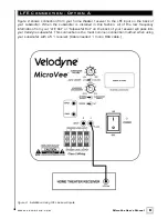
Page 9: ...connection is the most common connection method when using your subwoofer with a 5 1 receiver Cable needed 1 mono RCA cable Figure 2 Installation Using LFE Line Level Inputs LFE Connection Op tion A V...

Page 10: ...When one input channel is used instead of two the unit will see lower signal levels present at the inputs This may cause the unit to turn off inadvertantly when listening at low volume levels and or...

Page 11: ...into the thru jack on the back of the MicroVee subwoofer Cable supplied by Velodyne 6 foot 1 8 male to 1 8 male stereo cable Figure 3 Installation Using Mini Jack Line Level Inputs Mini Jack Connectio...

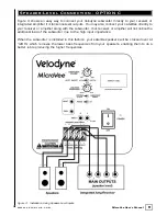
Page 12: ...amplifier along with the subwoofer Your receiver or amplifier will not notice the additional load of the subwoofer due to the high input impedance When the subwoofer is installed in this fashion your...

Page 13: ...o clean the cabinet During normal conditions your new subwoofer may be left on continuously without any problems The unit is equipped with a signal sensing turn on off that will automatically turn on...

Page 14: ...power button been depressed on the remote 7 Make sure binding posts are tightened If the protection circuitry is active the unit may cycle on and off until operating parameters return to normal Under...

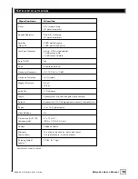
Page 15: ...on 5 typical Magnet Structure 64 oz 4 lbs Voice Coil 2 Dual Layer Inputs Speaker level mini jack and gold plated line level Outputs Speaker level 120 Hz high pass crossover mini jack thru Phase 0 or 1...

Page 16: ...DYNE is not responsible for damage caused by accidents abuse misuse natural or personal disaster or unauthorized modification The VELODYNE products are not intended for professional or commercial use...

Page 17: ...s DEQ 8R DEQ 10R DEQ 12R DEQ 15R DLS R Series DLS 3500R DLS 3750R DLS 4000R DLS 5000R Impact Series Impact Mini Impact 10 Impact 12 MicroVee 115 120V DD Series DD 10 DD 12 DD 15 DD 18 Digital Drive 18...

Page 18: ...Acoustics Inc 345 Digital Drive Morgan Hill CA 95037 408 465 2800 voice 408 779 9227 fax 408 779 9208 service fax www velodyne com Service E mail service velodyne com Product E mail help velodyne com...

Reviews: