Figure 9-9 Single Return Mode Timing Offsets (in µs)
Figure 9-10 Dual Return Mode Timing Offsets (in µs)
Figure 10-1 VLP-16 Configuration Screen
Figure 10-2 VLP-16 System Screen
Figure 10-3 VLP-16 Info Screen
Figure 10-4 VLP-16 Diagnostics Screen
Figure B-1 Velodyne Downloads Page
Figure B-2 Compare Firmware Versions
Figure B-3 Select New Firmware Image
Figure B-4 Upload New Firmware Image
Figure B-5 Firmware Update Complete Page
Figure B-6 Finalize Firmware Update
Figure B-7 Verify Firmware Versions
Figure C-1 Interface Box Mechanical Drawing 50-6001 Rev A
Figure C-2 VLP-16 and Puck LITE Mechanical Drawing 86-0101 Rev B1
Figure C-3 VLP-16 and Puck LITE Optical Drawing 86-0101 Rev B1
Figure C-4 VLP-16 and Puck LITE Optical Keep Out Zone 86-0101 Rev B1
Figure C-5 Puck Hi-Res Mechanical Drawing 86-0129 Rev A
Figure C-6 Puck Hi-Res Optical Drawing 86-0129 Rev A
Figure C-7 Puck Hi-Res Optical Keep Out Zone 86-0129 Rev A
Figure D-1 Interface Box Wiring Diagram 86-0107A
Figure D-2 Interface Box Schematic 69-8230A
Figure E-1 VeloView Open Sensor Stream
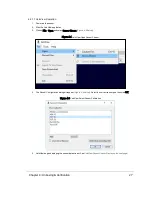
Figure E-2 VeloView Select Sensor Calibration
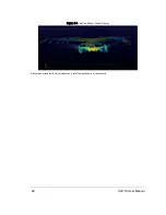
Figure E-3 VeloView Sensor Stream Display
Figure E-4 VeloView Record Button
Figure E-5 VeloView Open Capture File
Figure E-6 VeloView Play Button
Figure E-7 VeloView Spreadsheet Tool
Figure E-8 VeloView Data Point Table
Figure E-9 VeloView Show Only Selected Elements
Figure E-10 VeloView Select All Points
Figure E-11 VeloView List Selected Points
Figure F-1 Laser Diode Concept
Figure F-3 Laser Spots on a Wall
13


