Chapter 4 •
Unboxing & Verification
This chapter provides the procedure to test and verify that your sensor is operating properly. Do this to check out a new
sensor before permanently mounting it somewhere.
4.1 What’s in the Box?
22
4.1.1 Variants
22
4.2 Verification Procedure
22
4.2.1 Network Setup in Isolation
23
4.2.2 Access Sensor’s Web Interface
24
4.2.3 Visualize Live Sensor Data with VeloView
26
4.1 What’s in the Box?
A standard Velodyne VLP-32C sensor comes packaged in its own cardboard box.
Ensure all the components are present:
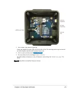
VLP-32C sensor in a protective shroud, with a fixed 3.0 m data/power cable terminated inside its Interface Box
AC/DC power adapter and 1.8 m AC power cord (once assembled, this is the power cord)
1.0 m Ethernet cable
Velodyne USB memory stick, containing:
User Manual
VeloView application installers for PC, Mac, and linux
Sensor sample data (i.e. pcap files)
Miscellaneous documents
4.1.1 Variants
Variants of the sensor exist, particularly with other connector types and/or cable lengths, and even without an Interface
Box. Your sensor (or the type you are interested in) may vary from the standard configuration above. Contact
Velodyne
Sales
for details.
4.2 Verification Procedure
The purpose of this procedure is to verify the sensor’s basic functionality and get you started on your way to processing
sensor data in (or from) the field. It involves one computer and one sensor in isolation at a workbench or desk. You’ll need
AC power. You won’t need a GPS receiver.
A video of the VLP-16 installation process is on YouTube at the following location:
https://www.y-
outube.com/watch?v=Pa-q5elS_nE
.
22
VLP-32C User Manual

