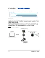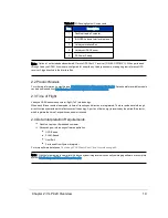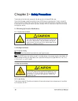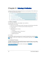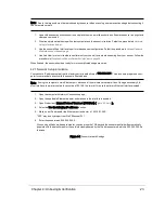
Note: Do not twist or otherwise adjust the strain relief gland nut where the interface cable enters the sensor. Adjusting
the position of the gland nut may damage the VLP-32C sensor internally.
5.4.1 Interface Box and Cable
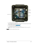
The standard VLP-32C sensor comes with an integrated cable that is terminated inside the Interface Box. The cable is
approximately 3.0 m in length and is permanently attached to the sensor.
Note: If you need to cut the integrated cable for any reason, please contact
Velodyne Sales
to get a waiver. Cutting this
cable could have warranty and RMA cost implications. Also, there is a minimum length requirement.
The Interface Box provides convenient connections for power, Ethernet, and GPS inputs. It protects the sensor from
power irregularities by incorporating a replaceable fuse and a reverse-current protection diode. When connected cor-
rectly to power, the diode allows current through to the sensor. If, however, the power and ground are switched, the diode
blocks current flow, protecting the sensor.
Opening the Interface Box and making modifications inside, such as replacing the fuse or reverse-current protection
diode, or repairing wires, is permitted.
For more information on the Interface Box, see
Interface Box Signals on page 40
.
5.4.2 Operation Without an Interface Box
The VLP-32C's Interface Box is a convenience, but it also adds bulk. The sensor may be ordered and used without the
Interface Box to accommodate the needs of the user. Contact
Velodyne Sales
for details (i.e. SKUs).
If used without the Interface Box, the user must provide sufficient reverse- and over-voltage protection circuitry to protect
the sensor. The schematic for the circuitry in the Interface Box can be found in
Wiring Diagrams on page 105
.
5.4.3 Power
The VLP-32C sensor does not have a physical power switch. The power source must be capable of providing as much as
3.0 A to accommodate the current surge that occurs during rotor spin-up when power is supplied to the sensor.
In normal operation the sensor draws between 9 and 18 W of power.
The
sensor's data sheet
specifies the input voltage that should be supplied to the unit. The sensor will not operate outside
that voltage range.
The power input jack on the Interface Box accommodates a 5.5 mm (O.D.) x 2.5 mm (I.D.) barrel connector. The center
pin has positive (+) polarity.
Note: Before operating the sensor, ensure it is securely mounted and that power will be applied in the correct polarity.
If the sensor doesn't spin up when power is applied, check the fuse, check the sensor's web interface if Laser is On and
Motor RPM is a valid value, check the input voltage, and make sure that the power source (battery, power inverter, or
power rail) is providing sufficient current. If they check out and yet the problem persists, get
Technical Support on page 92
.
Chapter 5 • Installation & Integration
31


