background image

User’s Manual

Remote Controlled 
Home Theater Subwoofers

Wi-Q10BV / Wi-Q10BVE
Wi-Q12BV / Wi-Q12BVE

Summary of Contents for Wi-Q10BV

Page 1: ...User s Manual Remote Controlled Home Theater Subwoofers Wi Q10BV Wi Q10BVE Wi Q12BV Wi Q12BVE ...

Page 2: ...hoosing a Velodyne Our passion for high performance low distortion bass is the driving force behind our worldwide reputation in audio and technical innovation We are pleased to bring the Velodyne sound experience to your home ...

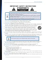
Page 3: ...are provided for your safety When the provided plug does not fit into your outlet consult an electrician for replacement of the obsolete outlet 12 Power Cord Protection Power supply cords should be routed so that they are not likely to be walked on or pinched by items placed upon or against them paying particular attention to cords at plugs convenience receptacles and the point at which they exit ...

Page 4: ...liance It has been designed in such a way that it does not require a safety connection to electrical earth 23 Flame Source No naked flame source such as lighted candles should be placed on the product 24 Battery The battery battery or batteries or battery pack shall not be exposed to excessive heat such as resulting from exposure to sunshine fire or the like Caution Danger of explosion if battery ...

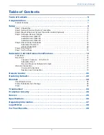
Page 5: ... Subwoofer Placement 12 Connect Subwoofer 12 Step 6 Run Auto EQ 13 Step 7 Set the Phase 13 Subwoofer Controls Connections Features 14 Front Panel 14 Rear Panel 15 Low pass Crossover 40 to 135 Hz 17 Subwoofer Direct 17 Receiver Processor Subwoofer Outputs 17 Alternate Connections 17 Line Level Connections 17 Speaker Level Connections 19 Remote Control 20 Restoring Defaults 22 Maintain 22 Check Repl...

Page 6: ...6 Wi Q User s Manual Intentionally Blank ...

Page 7: ... mounted 7 segment LED display One touch 5 band graphic equalizer with microphone included 4 selectable presets for customized listening mode Night mode setting Mute control Adjustable 40 to 135 Hz low pass crossover with Subwoofer Direct setting Speaker level inputs Line level inputs Switchable standby mode that activates when signal is absent Variable volume control with digital LED readout Sele...

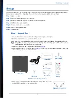
Page 8: ...aterials for future use Note Use this packaging if you ever need to move or ship the subwoofer to Velodyne for service Using other packaging may result in severe damage T o save storage space flatten the box and place the other packing material in a plastic bag 3 Record the serial number in the space provided on page 28 4 Make sure you have all the items shown in Figure 1 If any items are missing ...

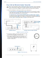
Page 9: ...ne stereo RCA cable Plug one channel of the RCA cable into the R input on the transmitter and the R output on your audio receiver Plug the other channel of the RCA cable into the L input on the transmitter and the L output on your audio receiver Figure 3 Transmitter connections 2 Plug the power adapter into the back of the transmitter Plug the other end of the adapter into a power outlet 3 Make su...

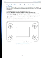
Page 10: ...ocations on the wall 2 Mark the two screw locations for either the horizontal or vertical mounting orientation 3 Hand turn each of the included self tapping wood screws into each marked location Tighten the screws until about 1 8 3 17mm of the screw shank is exposed Note The provided wood screws aren t suitable for stone or other hard wall surfaces If you can t hand drive the screws you may need t...

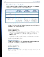
Page 11: ...he crossover frequency 5 Adjust the LFE SUB output level to 0 dB Audio Receiver Option 2 The audio receiver s full bandwidth R and L output channels are the input to the subwoofer less common case Use the audio receiver s speaker menu and set as follows 1 Select that you have no subwoofer 2 Select the number of speakers 3 Select the speaker size as large Audio Receiver Option 3 The audio receiver ...

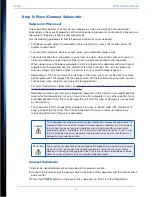
Page 12: ...Regardless of where you install your Velodyne subwoofer it must remain in an upright position woofer facing forward Do not use ship or store the subwoofer in any other position for an extended period of time this may damage the unit and this type of damage is not covered by the warranty The subwoofer is NOT magnetically shielded If you use it with an older CRT monitor or TV keep it at least two fe...

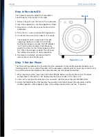
Page 13: ...turns to normal operation 6 T o prevent accidentally activating Auto EQ remove the mic from the Mic jack Step 7 Set the Phase The Phase setting optimizes the transition from the subwoofer to the satellite speakers based on your listening position You can adjust the phase of the subwoofer s output signal to correct any mismatch and the resulting cancellation between the subwoofer and your main spea...

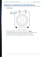
Page 14: ... are descriptions of the controls and connections shown in Figure 7 Remote Control Sensor IR sensor window receives a signal from the included remote control LED 2 5 digit seven segment LED readout displays volume phase and Auto EQ Mic Jack Connector for the supplied microphone to use during the Auto EQ process MIC Mic jack Remote control sensor LED ...

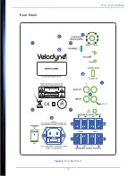
Page 15: ...15 Wi Q User s Manual Rear Panel Figure 8 Wi Q Rear Panel ...

Page 16: ...utput on your receiver processor Note When using the LFE output plug a single cable into the L LFE input or for more signal use a Y connector not included and feed the signal into both R and L inputs Stand By Mode Always On When this switch is in the STANDBY MODE position the subwoofer automatically turns itself on when an audio signal is present If there s no signal for about thirteen minutes the...

Page 17: ...l range audio signal for input when using our built in crossover Many home theater processors receivers Dolby Digital DTS THX have a subwoofer out jack sometimes labeled LFE that is internally filtered settable at the receiver processor and designed to be used with a powered subwoofer In some installations it is beneficial to use BOTH the Velodyne crossover and the receiver processor crossover to ...

Page 18: ...bwoofer s default volume setting is 30 out of 80 See your receiver s manual to adjust the LFE channel on your receiver or processor to achieve the desired bass output Figure 9 LFE Subwoofer Connection When using line level jacks use both the Left and Right inputs as shown in Figure 10 never use just the Left or Right input If using line level connections from a preamp or signal processor use both ...

Page 19: ...el connections use a high quality speaker cable that mates well with the connectors Be very careful to avoid any loose strands or frayed wires that may result in a short and damage your equipment Cables of extremely large size are not required due to the low current draw of this type of connection Extremely large gauge wire may not properly fit in the terminals and may result in a poor connection ...

Page 20: ... and then turns off again Night Limits the maximum dynamic output of the subwoofer for late night listening or considering close neighbors at any time Press the NIGHT button to turn night mode on off When you activate night mode the LED briefly displays n When you deactivate night mode the LED shows n off and then returns to normal function Volume Control Balances the output from the subwoofer to ...

Page 21: ...listening based on your sonic preference The following table lists the preset characteristics and musical style recommendations for each preset Preset Subsonic Filter Frequency EQ Frequency EQ Level Volume Differential Musical Style Recommendations Movies 25 Hz 37 Hz 3 db 5 db Action Adventure Movies R B Rock 28 Hz 50 Hz 3 db 1 db Country Rock Indie Music Pop Rock Classic Rock Dance and DJ Hard Ro...

Page 22: ... locate the fuse drawer slot at the base of the power cord connector 2 Insert a flat blade screwdriver in the fuse drawer slot and tilt the handle towards the subwoofer to open the fuse drawer Do not attempt to detach the drawer from the subwoofer The drawer contains two fuses an active fuse and a replacement fuse 3 Carefully remove the active fuse Hold it up to a light source and see if the condu...

Page 23: ...lamps DO NOT PUSH OBJECTS OF ANY KIND into the subwoofer or transmitter DO NOT PLACE BURNING CANDLES INCENSE OR SMOKING PRODUCTS ON TOP OF OR NEAR THE SUBWOOFER OR TRANSMITTER DO NOT PLACE A LAPTOP COMPUTER ON TOP OF THE SUBWOOFER OR TRANSMITTER Damage could occur to either the laptop hardware or the subwoofer finish Clean USE A CLEAN SOFT DRY CLOTH to remove dust or fingerprints from the subwoofe...

Page 24: ...es bypass this and there will be no output at these terminals 8 Verify that the subwoofer is not in mute mode by pressing the MUTE button on the remote control Bass doesn t sound loud enough 1 Increase the subwoofer s VOLUME level 2 Increase the receiver s LFE or SUB OUT volume level if it s adjustable 3 Put the subwoofer closer to a corner of your room Subwoofer output is distorted intermittent o...

Page 25: ...ypically it takes at least 10 minutes for the subwoofer to cool down and recover from a thermal shutdown Also plug the unit into a different wall socket Overloaded sockets or damaged home wiring circuits can cause power voltage drops while the subwoofer is drawing high power levels This condition can result in the subwoofer shutting down intermittently Service DO NOT ATTEMPT TO SERVICE THE SUBWOOF...

Page 26: ...b 7 40 lb High Pass Crossover 80 Hz 6 db octave 80 Hz 6 db octave Low Pass Crossover 40 135 Hz adjustable 12 dB octave 24 dB ultimate 40 135 Hz adjustable 12 dB octave 24 dB ultimate Outputs Gold plated line level Nickel plated speaker level Gold plated line level Nickel plated speaker level Inputs Gold plated line level Nickel plated speaker level Gold plated line level Nickel plated speaker leve...

Page 27: ...ntrolled environment This equipment should be installed and operated with minimum distance 20cm between the radiator your body IC warning English This device complies with Industry Canada licence exempt RSS standard s Operation is subject to the following two conditions 1 This device may not cause interference and 2 This device must accept any interference including interference that may cause und...

Page 28: ...where you purchased this subwoofer Trademarks The Velodyne logo is a trademark of Velodyne Acoustics Inc All other trademarks are the property of their respective owners For Your Records Note If you need to file a warranty claim for your product you still need to submit either of the following to Velodyne Original sales invoice Other proof of ownership and date of purchase Please validate your pro...

Page 29: ...Jun13 Velodyne Acoustics Inc 345 Digital Drive Morgan Hill CA 95037 www velodyne com Voice 408 465 2800 Fax 408 779 9227 Service fax 408 779 9208 Service e mail service velodyne com General e mail help velodyne com ...

Reviews: