background image

FIG. J

FIG. K

6

7

M

a

x 8

0

c

m

Max 30

°

FIG. H

    NOTE

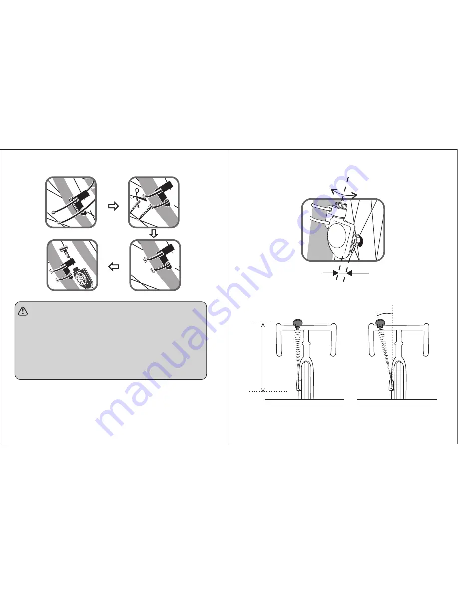
The  distance  between  magnet  and  sensor 

should be no more than 5mm 

(Fig.I).

The  sensor  should  face  the  computer,  the 

distance  between  sensor  and  computer 
shoubld  be  no  more  than  80cm  (FIG.J),  the   
angle should be no more than 30

°

(FIG.K).

FIG. I

Angle adjustment

Max5mm

Copyright © 2010 www.Veloset.co.uk  UKET limited

Summary of Contents for JS-204

Page 1: ...xercise can t be used as medical indicator PRODUCT GUIDE FIG A 1 Wireless Cycle Computer Wireless cycle computer with wireless heart rate monitor Wireless cycle computer JS 204 JS 212 JS 212A JS 204A...

Page 2: ...rt I How to install the computer How to install the battery of computer 1 How to install the battery of 9S 204 9S 204A Wrest the 4 screws on the back of computer remove the back case and put the batte...

Page 3: ...f buckle and push the computer out through the slot FIG D nylon cords computer bracket rubber slip bicycle gripe Part III Magnet installation Fasten the magnet with screw to the spoke of the wheel FIG...

Page 4: ...nd sensor should be no more than 5mm Fig I The sensor should face the computer the distance between sensor and computer shoubld be no more than 80cm FIG J the angle should be no more than 30 FIG K FIG...

Page 5: ...12 JS 212A JS 204 DST Display JS 204A Distance SPD Functions Clock Speed 9 BUTTONS 1 MODE 1 Functions switch Speed Clock Distance Ridind time Temperature Pulse Average speed Max speed ODO Scan RTM TEM...

Page 6: ...n the case back It will light for around 5 seconds by every pressing FIG M HOW TO MEASURE THE BIKE CIRCUMFERENCE Use tapeline to measure the diameter of front bike wheel Or you can calculate the bike...

Page 7: ...get the bike circumference SPEED UNIT CIRCUMFERENCE CLOCK SETTING 1 Replace the battery or press SET and MODE together for 2 seconds KM H will flash and enter into setting speed unit 2 Press and hold...

Page 8: ...ES relative speed MXS max speed and enter SCAN mode 2 The measurement begins once riding on the bicycle If the computer receive no signal during riding the in the display will not flash Stop riding an...

Page 9: ...see FIG Q Note If you wear the heart pacemaker or any other medical equipment please do not measure heart rate Please do not measure heart rate near FIG P ensure a solid contact 2 Strap the belt acros...

Page 10: ...S i Upper line shows that your current riding speed is 20 2km h ii Lower line shows that your riding distance is 3 Press MODE again and switch to the display as FIG T i Upper line shows your current r...

Page 11: ...ore than 9H59M59S the max time for memory the average speed KM H SPD TEMP 20 FIG W FIG V will display incorrectly Please clear both exercise time and distance to zero to get a correct value of the ave...

Page 12: ...TING GUIDE Problem Cause Solution Problem Cause Solution Re install the computer Re install the battery correct or replace the new battery No power of sensor or computer The computer can not receive a...

Reviews: