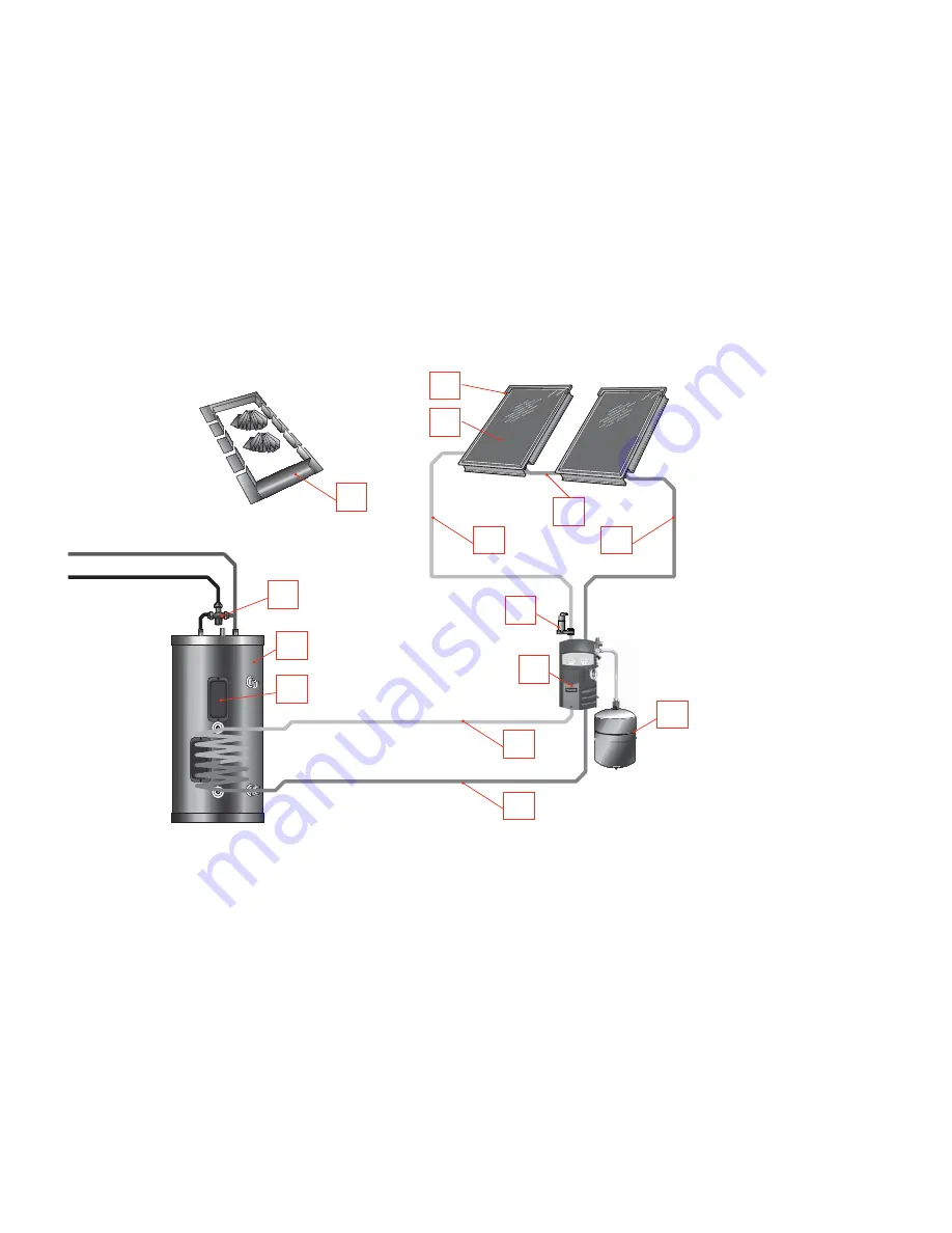
VELUX solar water heating system with electric or gas back-up – Part 3: Solar water heater system installation – 7
Cooled glycol
Heated glycol
VELUX solar water heating system with electric or gas back-up
System models: CLI U12 SD0(W/L/F/P) 118 El B/U
CLI U12 SD0(W/L/F/P) 1110 NG B/U CLI U12 SD0(W/L/F/P) 1111 LP B/U
CLI U12 SK0(W/L/F/P) 218 El B/U
CLI U12 SK0(W/L/F/P) 2110 NG B/U CLI U12 SK0(W/L/F/P) 2111 LP B/U
CLI U12 SK0(W/L/F/P) 318 El B/U
Notes:
1.
This drawing is meant to show a system piping concept only. The installer is responsible for all equipment and detailing by local codes.
2.
Anti-freeze, non- potable heat transfer fl uid shall be used for the solar storage tank heat exchanger circuit only. Never introduce Anti-freeze solution to any
other solar storage tank connection other than the solar heat exchanger.
3.
If there is a check valve on the cold water feed line, a thermal expansion tank suitable for potable water must be sized and installed within this piping system
between the check valve and the cold water inlet of the solar storage tank.
4.
The an anti-scald mixing valve provided must always be installed as shown.
5.
For all electric back-up models, make sure solar storage tank is fully purged of air before power is turned on to the back-up heat source.
8.
11.
7.
6.
5.
9.
4.
2.
3.
1.
10.
4.
4.
4.
1. Collectors
2. Flashing/racking
3. Connector
tube
4. Flextubes
5. Air
Separator
6. Pump
station/controller
7. Expansion
tank
8. Solar storage tank
9. Mixing
valve
10. Temperature sensor
11. Electric auxiliary with
thermostat
Cold water
Hot water


