background image

483515 • DFDR FDR FSDR, Rev. 3, January 2022 

Copyright 2022 © Venco Products

8

As a result of our commitment to continuous improvement, Venco reserves the right to change specifications 

without notice.

Our Commitment

Phone: 1.833.881.0565 • Fax: 715.355.2399 • E-mail: info@vencoproducts.com • Website: www.vencoproducts.com

Damper Maintenance

Dampers do not typically require maintenance as long as they are kept dry and clean. If cleaning is necessary, use 
mild detergents or solvents. If lubrication is desired for components such as axle bearings, jackshaft bearings and 
jamb seals, do not use oil-based lubricants or any other lubricants that attract contaminants such as dust.
Dampers and their actuator(s) must be maintained, cycled, and tested a minimum in accordance with:
  • The latest editions of NFPA 80, 90A, 92, 101, 105, UL864, AMCA 503-03 and local codes.
  • Actuator manufacturer recommendations.

Damper Troubleshooting

The following is a possible cause and correction list for common concerns with dampers.

Symptom

Possible Cause

Corrective Action

Damper does not 
fully open and/or 
close

Frame is 'racked' causing blades to 
bind on jamb seals

Adjust frame such that it is square and plumb

Actuator linkage loose

Close damper, disconnect power, adjust and 
tighten linkage

Defective motor

Replace

Screws in damper linkage

Damper installed too far into wall. Move out to 
line as designated on damper label

Contaminants on damper

Clean with a non-oil based solvent (see Damper 
Maintenance)

RRL or TOR sensor 
tripped

Heat

Push reset button located on backside of RRL or 
TOR

Damper does not 
operate

No power supplied to the actuator

Add power supply

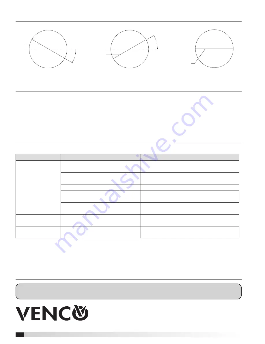
Blade Orientation

Axle

30°

30° Off Horizontal (Maximum)

Axle

30°

30° Off Horizontal (Maximum)

Axle

Normal

Summary of Contents for DFDR Series

Page 1: ...eiving and Handling Upon receiving dampers check for both obvious and hidden damage If damage is found record all necessary information on the bill of lading and file a claim with the final carrier Ch...

Page 2: ...terials include but are not limited to a Mortar dust b Drywall dust c Firesafing materials d Wall texture e Paint overspray 7 Damper should be sufficiently covered as to prevent overspray if wall text...

Page 3: ...rs must meet the requirements of the appropriate wall design See UL Fire Resistance Directory and or local codes Figure 1 12 in 24 in o c Maximum Floor Runner 2 in Ceiling Runner 2 Panhead Screws 24 i...

Page 4: ...assembly to allow for this expansion The wall floor opening must be a minimum of 7 8 in 22mm larger than the outside diameter of the damper Clearances Required Between Damper Sleeves and Wall Floor O...

Page 5: ...ITION INDICATOR AND OR ELECTRIC LINK DUCT CONNECTION AREA 2 00 IN 1 50 IN Optional Second Retaining Plate Do not place retainer plate in this groove Figure 5 FSDR SEFSDR SSFSDR Inserting Damper into W...

Page 6: ...p for easy installation when the clamping screw is loosened If necessary remove the clamping screw and nut see Figure 7 Position the retaining plate between the blade axle and the actuator shaft as sh...

Page 7: ...ensor with the lower temperature setting can be bypassed by an external contact closure allowing the damper to reopen until the secondary temperature is reached the sensor with the higher temperature...

Page 8: ...he latest editions of NFPA 80 90A 92 101 105 UL864 AMCA 503 03 and local codes Actuator manufacturer recommendations Damper Troubleshooting The following is a possible cause and correction list for co...

Reviews:

Related manuals for DFDR Series