2019.10
15 / 31
Figure 8.6.Ground label
Figure 8.7. Fan label
Figure 8.8.Electrical warning
label
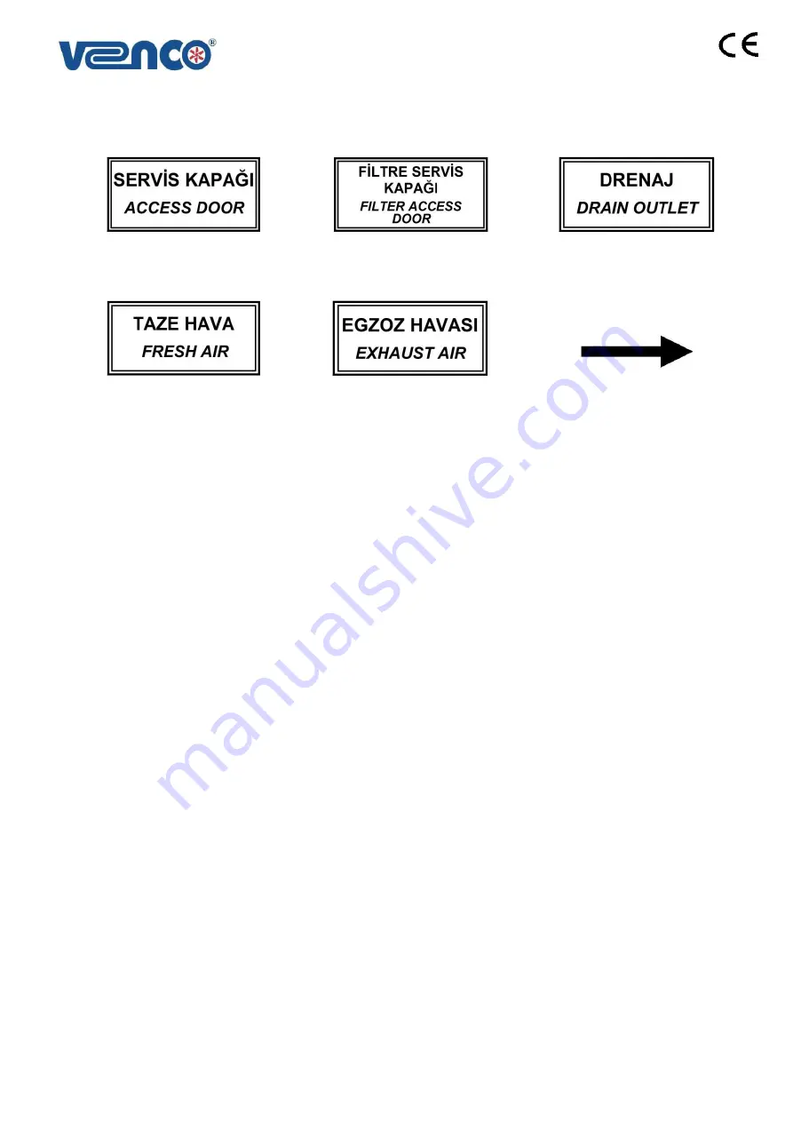
Figure 8.9. Access door label
Figure 8.10. Filter access door
label
Figure 8.11. Drain label
Figure 8.12. Fresh air label
Figure 8.13. Exhaust air label
Figure 8.14. Air flow direction
label
9. CONTROLS BEFORE START-UP
Please make sure that all electricity cables are made according to (EN 60204 -1) standards and security
and protection units belong to all elements.
Please make sure that all parts of the unit are clean. There can be duct insulation residuals, bands etc.
If the outside temperature is less than -
5°C, the unit must be stopped and you should contact with VENCO.
The condense water can be frozen at the temperature less than -
5°C, it can be damaged to the exchanger.
Following points have to be controlled periodically.
Isolation materials used for heat and sound isolations
Cable isolation
Control panel
Electrical cables and other electromechanical parts
Metal and painted surfaces
Connection elements such as screw, turn screw and joint washer
FILTERS;
Maintenance of the filters should be done regularly. Dirty filters can decrease air flow and
consequently the capacity. Synthetic or metal filters can be cleaned or washed. However it is advised to change
synthetic filters every two years. While changing other type filters; bag, hepa filters with the new ones, new
ones should have same dimension, type and features.
HEAT RECOVERY EXCHANGER;
is controlled before transportation. The plates of heat recovery exchanger
should be checked, after transportation.
FANS and MOTORS;
Wiring shall be done, according to international standards. The turning way of fan-blades
should be checked, according to the air-flow direction label on the fan.
Summary of Contents for VHR Series
Page 8: ...2019 10 8 31 Table 3 2 Dimensions for VHR and VHR EC Models...
Page 23: ...2019 10 23 31 17 APPENDIX 17 1 APPENDIX 1 Standard Controller SEC Electrical Wiring Diagram...
Page 24: ...2019 10 24 31 17 2 APPENDIX 2 Functional Controller FEC AC FAN Electrical Wiring Diagram...
Page 25: ...2019 10 25 31 17 3 APPENDIX 3 Functional Controller FEC EC FAN Electrical Wiring Diagram...


