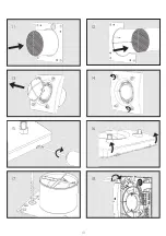
7
• Do not obstruct the fan or exhaust grille to ensure optimum air passage.
• Ensure adequate air return/discharge into/from the room in compliance with existing regulations in order to ensure proper device operation.
• If the environment in which the product is installed also houses a fuel-operating device (water heater, methane stove etc., that is not a “sealed chamber” type), it
is essential to ensure adequate air intake, to ensure good combustion and proper equipment operation.
In both versions, the unit pulls air out for 70 seconds, then it pushes air in for the same time.
When heated air is pulled (extracted) from inside the room, it warms up the heat exchanger; when the cold air is pushed (supplied) in the room, it gets preheated,
recovering most of thermal energy which would be otherwise lost in the ventilation process.
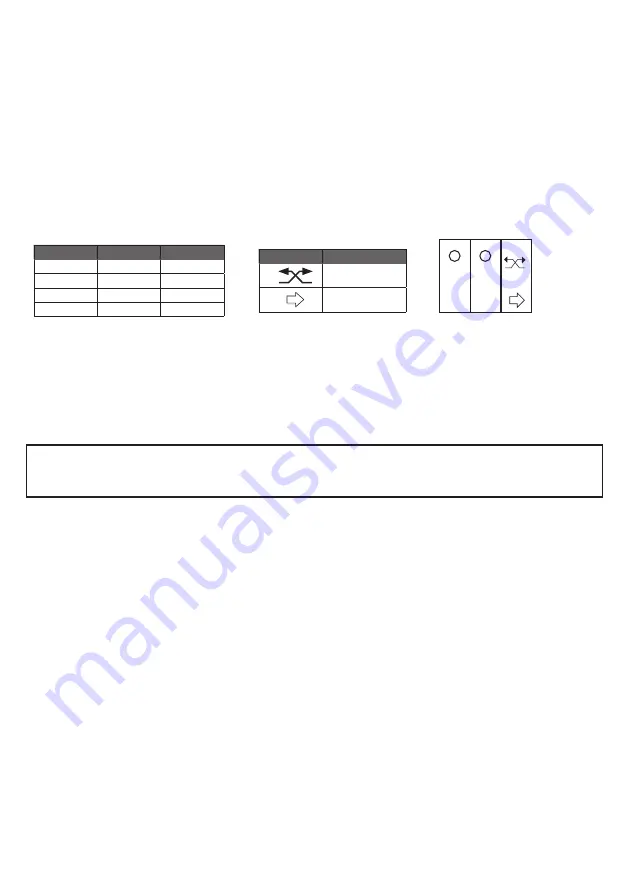
The unit runs at the speed selected by activating the two-position switches “S1”, “S2” and “S3” of the CTRL-S (accessory Fig. 64). The same functionality can be
achieved with CTRL-S or with 3 two-position switches.
S3 switch activates the “Free cooling “ (Bypass) mode , which stops alternate flow and keeps the fan in”extract-only” or “intake-only”mode, to avoid the heat
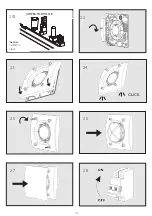
exchange when necessary. To set the “extract-only” mode or “intake-only”, place the integral jumpers as per fig. 21A or Fig. 21B. The front cover LED indicates
when the Free cooling mode is on.
An automatic “Boost”mode can be achieved through a dedicated switch or room sensors like SEN-HY, SEN-PIR or SEN-CO2, connecting such switch in parallel to
the S2 switch.
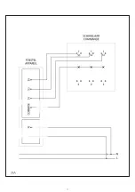
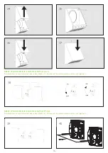
Wiring diagram of the unit: Fig. 19A
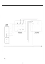
Wiring diagram with ambient sensors: Fig.19B and Fig. 19C.
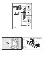
Wiring diagram of two or more units: Fig. 19D.
“S1”
“S2”
Operation
O
O
OFF
I
O
Speed 1
O
II
Speed 2
I
II
Speed 3
“S3”
Operation
Heat recovery
(Alternate flow)
Free cooling
(Extract only)
Externa
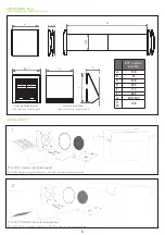
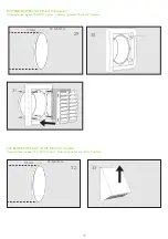
l grille in high quality, impact and UV-resistant ABS colour RAL 9010.
or external hood
in aluminium, painted in white (RAL 9010), acoustically lined.
When the units are installed in pair, they must be synchronised so that when one unit is extracting, the other is supplying, and viceversa. This is achieved by setting
the dedicated jumper. (Fig. 21A-21B).
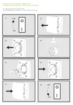
RESET OF THE SYNCHRONISATION
OPTION 1
If two or more units are connected under the same main switch, to reset the synchronisation, the main switch must be switched first OFF and the ON to
reactivate (fig.38)
OPTION 2
If two or more units are not connected under the same main switch, to reset the synchronisation, press at the same time the black pin of each unit (Fig.40)
for at least 3 seconds.
SYNCHRONISATION
WARNING:
Ensure that the electric wiring to L and N is done correctly; an incorrect connection will lead to malfunction or
permanent damage of the fan
VERSIONS
OPERATION
S1
S2
S3
II
I
STANDARD CONFORMITY
2006/95/EC Low Voltage Directive (LVD) and 2004/108/EC Electromagnetic Compatibility (EMC), in conformity with the following standards:
Electrical Safety EN60335-1(2008); EN 60335-2-80(2005); EN 60335-2-80/A2(2009)
Electromagnetic Compatibility EN 55014-1(2006)+A1+A2; EN 55014-2(1997)+A1(2001)+A2(2008)+IS1(2007), EN 61000-3-2(2006)+A1(2009)+A2(2009); EN
61000-3-3(2008).
Maintenance can be carried out by the user as indicated at page 15
Service must be performed only by technically qualified personnel in accordance with local rules and regulations. Make sure that the mains supply to the unit is
disconnected (page 16). Cleaning of the heat exchanger can be performed from outside as well.
MAINTENANCE AND SERVICE
POSITION JUMPER
Integral jumper set in position A (Fig.21A) means “extract-only” mode.
Integral jumper set in position B (Fig.21B) means “intake-only” mode.
The jumper position defines both the air-flow direction when the unit is activated for the first time (for the synchronisation) and the air-flow direction of the
free-cooling mode.
Summary of Contents for Mini eco Comfort
Page 10: ...10 11 13 14 15 17 18 12 115mm 16...
Page 11: ...11 19A...
Page 12: ...12 19B...
Page 14: ...14 21B 22 25 23 JUMPER POSITION B 24 CLICK 26 27 28 Toevoer Insufflation Intake...


