


13
Fig. 8
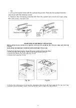
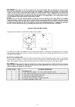
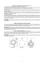
2) Burner "MINIMUM" adjustment:
Work surface burner adjustment
: follow the instructions below to adjust the work surface burner minimum:
1) Light the burner and set the knob to the MINIMUM position (small flame).
2) Remove the knob of the valve that is press fit on the rod of that valve.
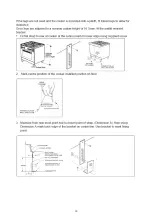
3) If the cooker is not equipped with safety valves on the surface burners, insert a small slotted screwdriver into the hole
on the valve rod (Fig. 14) and turn the choke screw to the right or left until the burner flame is adjusted to minimum. If the
cooker is equipped with safety valves, the choke valve is not located in the rod hole but on the valve body (Fig. 15).
4) Ensure sure that the flame does not go out when switching quickly from the MAXIMUM to the MINIMUM position.
Fig. 14
Fig. 15
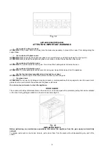
APPLIANCE ELECTRIC CONNECTION
The electric connection must comply with the current legal standards and regulations.
Before making the connection, check that:
¾
The system electrical rating and the current outlets are adequate for the maximum power output of the
appliance (see the label applied to the bottom of the casing).
¾
The outlet or the system is equipped with an efficient ground connection in accordance with the current legal
standards and regulations. The manufacturer will not be responsible for the non-compliance with these
instructions.
¾
The power cord is supplied with a 15A plug, suitable for the load indicated on the label and a standard 15A
GPO.


