background image


16

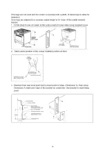
To replace parts such as nozzle supports, valves and electric components follow the procedure described in the burner 
adjustment paragraph. To replace the valve or the gas thermostat, it is also necessary to disassemble the two rear gas 
train brackets, loosening the 4 screws (2 per bracket) that attach it to the rest of the cooker and, unscrew the nuts that 
attach the front burner valves to the control support, after removing all the knobs. To replace the gas or electric 
thermostat, also disassemble the rear cooker guard, loosening the relative screws, to be able to pull out and reposition 
the thermostat bulb. 
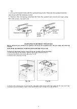
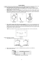
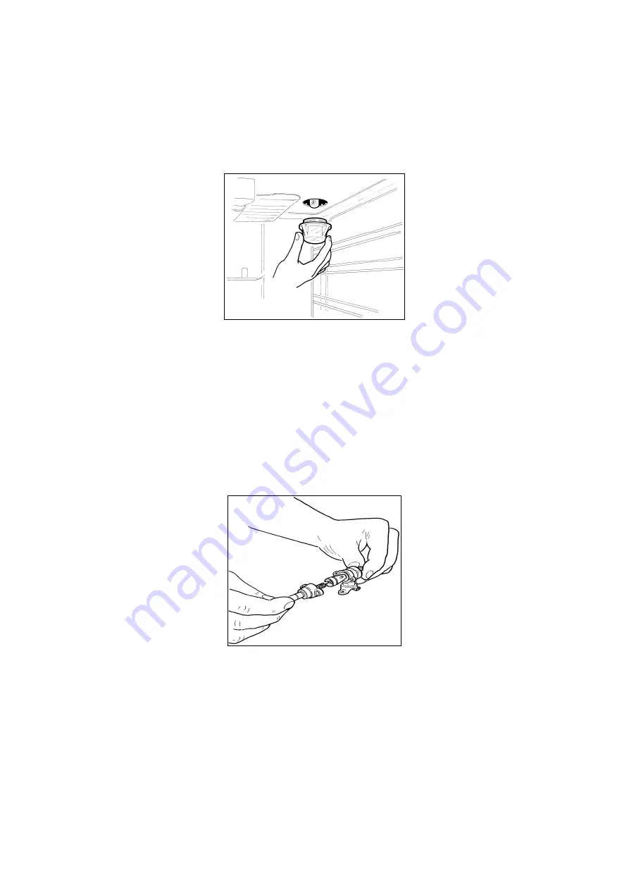
To replace the oven bulb, just unscrew the protection cap that projects out inside the oven. (Fig.19) 


                       Fig. 19


WARNING:

 Before replacing the bulb, disconnect the appliance from the electric power supply. 

WARNING:


The power cord supplied with the appliance is connected to the appliance with an 

X

 type connection (in 

compliance with standards AS/NZS 60335-1, AS/NZS 60335-2-6 and subsequent amendments) for which it can be 
installed without the use of special tools, with the same type of cord as the one installed. 
If the power cord becomes worn or damaged, replace it based on the information reported in table 4. 

WARNING:

 If the power cord is replaced, the installer shall ensure that the ground cable is longer than the 

phase cables and also should comply with the warnings regarding the electric connection. 
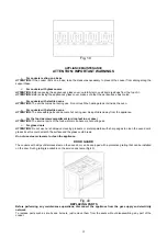
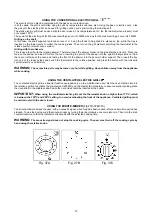
Greasing the valves: 

If it becomes difficult to operate the valve, it should be greased immediately by following the instructions listed below: 
 
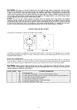
1) Disassemble the valve body by loosening the two screws located on the body of the valve (Fig.20)


                         Fig. 20


2) Extract and clean the seal cone and its housing with a rag soaked with thinner. 
3) Lightly grease the cone with special grease. 
4) Insert the cone, moving it several times, remove it again, remove the excess grease and make sure that the gas 
passage ways are unobstructed. 
5) Replace all the pieces by reversing the order in which they were disassembled and check that the valve operates 
correctly. 
6) To replace the power cable, lift the terminal board’s cover and replace the cable. To access the terminal board in 
cookers with a 3x2.5mm² cable, the back panel on the rear of the appliance must be removed.  


Summary of Contents for VEF61EG

Page 1: ...erty or to persons caused by incorrect installation or improper use of the appliance The manufacturer is not responsible for any inaccuracies due to printing or transcription errors contained in this...

Page 2: ...l description 15 Using burners 16 17 Use of electric plates 17 18 Using the ceramic hob 18 Using the gas oven 18 20 Using the thermostat with switch in series 21 Using the electric thermostat 21 Using...

Page 3: ...3...

Page 4: ...point for recycling of electrical and electronic equipment Disposal must be carried out in accordance with local environmental regulations for waste disposal For more detailed information about treat...

Page 5: ...2 Class 1 Installation or inserted between two walls Fig 1 Class 2 Subclass 1 Installation A single sidewall that exceeds the height of the work surface is possible This must be at a minimum distance...

Page 6: ...the quantity of air needed should be based on the regular combustion of gas and on the ventilation of the room Natural air will flow through permanent openings in the walls of the room to be ventilate...

Page 7: ...k of the appliance indicates the appliance adjustment conditions type of gas and operating pressure IMPORTANT This appliance must be installed in compliance with current national standards in force an...

Page 8: ...8 Table 1...

Page 9: ...9...

Page 10: ...10...

Page 11: ...11...

Page 12: ...below to change the burner nozzles on the work surface 1 Pull out the plug from the electric outlet to avoid any type of electric contact 2 Remove the grids from the work surface Fig 7A 7B 3 Remove th...

Page 13: ...d hole but on the valve body Fig 15 4 Ensure sure that the flame does not go out when switching quickly from the MAXIMUM to the MINIMUM position Fig 14 Fig 15 APPLIANCE ELECTRIC CONNECTION The electri...

Page 14: ...ven 3x1mm M6 3x1 5mm M9 Ventilated Electric Oven 3x1 5mm Gas oven Gas grill 3x1mm Gas burner 1 hot plate Gas oven Electric grill 3x1 5mm M6 3x2 5mm M9 Electric Oven 3x1 5mm M6 3x2 5mm M9 Ventilated El...

Page 15: ...ildren away from the appliance For the food warmer compartment or drop leaf in our case ATTENTION The internal parts of the food warmer can become hot during use For glass doors ATTENTION Do not use h...

Page 16: ...talled without the use of special tools with the same type of cord as the one installed If the power cord becomes worn or damaged replace it based on the information reported in table 4 WARNING If the...

Page 17: ...he control panel small symbols show the function of each knob or key Here are the several controls that a cooker can have Shows the position of burners on the worktop the full dot identifies the burne...

Page 18: ...a star and release it as soon as the burner has ignited Fig 23 A Fig 23 B Fig 23 C Burner ignition equipped with safety device thermocouple Fig 22 Turn the knob anticlockwise that corresponds to the...

Page 19: ...positions Fig 24A 24B Fig 24A Fig 24B The plates can be utilised by rotating the knob onto the desired position On the front of the appliance there is a design showing which plate the knob refers to...

Page 20: ...rolled by a thermostat or by an energy regulator that is used to select a variable temperature When the boiling point is reached the temperature can be reduced to allow the food to slowly boil Practic...

Page 21: ...evice In this case first open the oven door and then turn the knob to the maximum temperature setting number 8 Then press the thermostat knob models with ignition through the knob Wait about 10 second...

Page 22: ...side with the raised backstop towards the rear of the oven Temperatures between brackets are referring to the use of oven with fan assisted gas TABLE N 8 GAS OVEN COOKING TABLE TEMP C HEIGHT MINUTES...

Page 23: ...en turned on or indicates that only the top external element 900W M6 1200 W M9 has been turned on or indicates that only the grill element 1500WM6 1800W M9 has been turned on In these positions the te...

Page 24: ...ferent types of oven operation Fig 31A Fig 31B Fig 31C For type VEF61EG or indicates that only the oven light is turned on or indicates that the bottom element 1300W and the top external element 900W...

Page 25: ...PUFF PASTRIES 200 220 3 15 20 RAISIN LOAF 250 3 25 35 STRUDEL 180 3 20 30 SAVOIA COOKIES 180 200 3 40 50 APPLE FRITTERS 200 220 3 15 20 SAZOIARDI SANDWICH 200 220 3 20 30 TOAST SANDWICH 250 4 5 BREAD...

Page 26: ...Fig 26A Fig 26B Fig 26C Fig 26D The grill burner always operates at maximum and therefore there is no minimum position In addition it is equipped with a safety device to prevent the flame from going...

Page 27: ...s at level 3 Place the food on the skewer and insert this into the oven placing the point of the skewer into the spindle that projects out from the rear or left size of the oven and resting the front...

Page 28: ...he skewer holder support Then insert the tray into one of the lower guides and switch the thermostat to the relative position and press the button with the rotisserie symbol electric oven version WARN...

Page 29: ...time of day cooking end time the relay output and the cookpot symbol are switched off The audible signal sounds The symbol A blinks Semi automatic operation with cooking end time Select the cooking en...

Page 30: ...r lemon juice salt tomato sauce etc and do not wash the enamelled parts while they are still hot Cleaning the STAINLESS steel parts Clean the parts with soapy water and then dry them with a soft cloth...

Page 31: ...hould be performed by skilled personnel For this reason we advise the customer to contact the Retailer that sold the appliance or the Customer Care Team on 1800 444 357 providing them with information...

Reviews: