


29
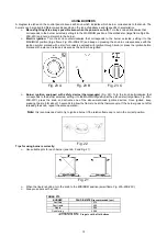
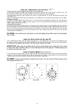
ANALOGUE CLOCK WITH TIMER
(Fig. 38)
The analogue clock with timer lets you know when the cooking is finished thanks to an acoustic signal.
To set the clock, push and turn the pivot clockwise until you reach the chosen time; release the pivot, then turn it
clockwise again (without pushing) until the ring is positioned on the crossed bell: in this way only the clock will be
functioning.
To use the timer, turn the pivot clockwise without pushing and choose, using the ring, the cooking time; once the time is
over the clock will alert you with an acoustic signal.
PLEASE NOTE that the acoustic signal does not interrupt the cooking process. To stop it, it is necessary to
switch off manually with the corresponding buttons.
Fig.38
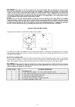
ELECTRONIC TIMER
(Fig. 39)
Setting
Select a function by pressing the function button and set the required time with the +/- buttons.
+/- buttons
Pressing the “+” button increases the time set, pressing “-“ decreases it. The count-up and count down speed increases
the longer the button is held in the appropriate position
Setting the time of day
Select the time of day function by pressing the duration and end time button together and set the time of day with the +/-
buttons.
Any programme which has been set is cancelled and the outputs switched on
Manual operation
Press duration and end time button together. The relay contacts will switch on. The “A” symbol will be erased, the pot
symbol illuminated. Any programme which has been set is cancelled.
Semi-automatic operation with cooking duration
Select the cooking duration function and set the required duration with +/- button. “A” and cookpot symbol appear. The
relay output becomes active. If time of day = cooking end time the relay output and the cookpot symbol are switched off.
The audible signal sounds. The symbol “A” blinks.
Semi-automatic operation with cooking end time
Select the cooking end time function and set the required duration with +/- button. “A” and cookpot symbol will appear.
The relay output becomes active. If time of day = cooking end time the relay output and the cookpot symbol are switched
off.
The audible signal sounds and “A” blinks.
Fully automatic operation
Select the cooking duration function and set the required duration with +/- button. The “A” symbol appears. The relay is
switched on and the cookpot symbol appears. Select the cooking end time function and the earliest possible end time is
displayed. Set the required end time with the +/- buttons. The relay and the cookpot symbol are switched off.
The cookpot symbol appears again when time of day = the calculated start time.
After the automatic programme has ended, the symbol “A” blinks.
The audible signal is heard and the cook pot symbol and the relay are switched off.
Minute minder
Select the minute minder button and set required time with the +/- buttons. As the time set elapses the bell symbol is
displayed. After the time set has elapsed, the audible signal sounds.
Audible signal
The audible signal sounds at the end of a minute minder cycle or of a cooking programme for a period of 7 minutes. The
signal can be cancelled by pressing any function button. Pressing the “-“ button without having previously selected a
function the frequency of the signal changes. A selection from 3 possibilities can be made. The selected signal is audible
as long as the time the “-“button is pressed.
Programme start and verification
A programme which has been set is carried out after setting the time required. The “time to run” can be verified at any
time by selecting the appropriate function.