


6
IMPORTANT INFORMATION FOR INSTALLING THE APPLIANCE
The cooker can be installed separately, as a freestanding unit, or between kitchen units or between a kitchen
unit and the wall. The device must be installed in accordance with the regulations stated in UNI 7129 and UNI
7131 standards.
This appliance is not connected to devices which exhaust combustion products.
Special attention must be focused on the prescriptions described below regarding room aeration and
ventilation. Any hanging cabinets installed above the work surface must be located at a distance of no less than
700 mm.
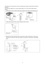
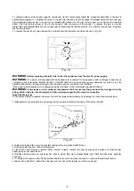
ROOM VENTILATION
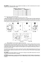
To ensure that the appliance operates correctly, the room where it is installed must be continuously ventilated. The room
volume should not be less than 25 m³ and the quantity of air needed should be based on the regular combustion of gas
and on the ventilation of the room. Natural air will flow through permanent openings in the walls of the room to be
ventilated. These openings will be connected with the outside environment and should have a minimum cross-section
defined by the current national standards regarding room ventilation (Fig. 3).
These openings should be built so that they cannot be clogged.
Indirect ventilation is also permitted by taking air from the rooms adjacent to the one to be ventilated.
Fig. 3
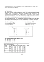
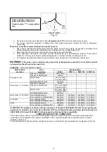
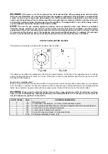
LOCATION AND AERATION
Gas cooking appliances must always evacuate the combustion products by means of hoods connected to chimneys,
flues or directly outside (Fig. 4). If a hood cannot be installed, it is possible to use a fan installed on a window or directly
facing outdoors, to be operated together with the appliance (Fig. 5), provided that there is strict compliance with the
ventilation regulations.
Fig. 4
Fig. 5