background image

7

8. INSTALL 

HOOD

WARNING

!

Be careful when installing the decorative flue and hood, they may have sharp edges.

CAUTION

DO NOT REMOVE the protective plastic film covering the decorative flue (upper and lower) and the hood yet.

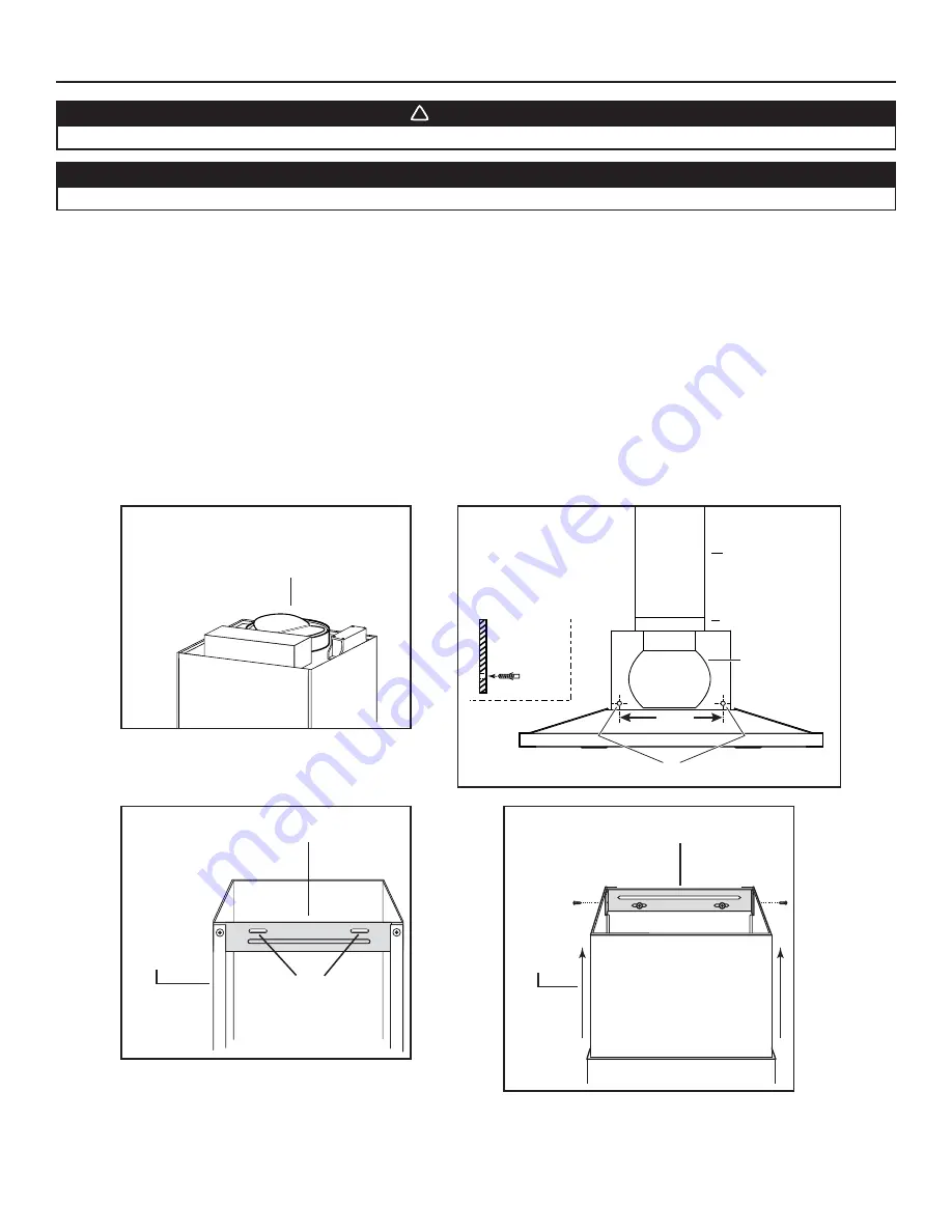
1.  Install 6" round adapter/damper on top of the hood using 4 no. 8 x 7/16" mounting screws (

Fig. 1

).

2.  Align the hood and center it above the hood mounting bracket. Gently lower the hood until it securely engages the bracket.

3.  With the hood hanging in place, drill through both holes located in the inside lower back of hood (

Fig. 2

) using a 5/16" drill bit. Insert 

the included drywall anchors into the drilled holes (one for each hole). Insert 2 no. 8 x 1¼" mounting screws in 2 washers (one per 
washer), then insert into the drywall anchors. Verify that the hood is centered and leveled. Tighten all screws completely.

4.  Remove protective plastic film covering the lower flue only.

5.  If possible (when space is sufficent): Install the lower flue bracket to its flue using 2 no. 8 x 7/16" mounting screws, ensure that the slots 

point up (

Fig. 3

).

6.  Carefully place both flues into the recessed area of hood top.


NOTE: Slightly slide up the upper flue to avoid damaging it.

7.  Slide a 6" steel round duct over the adapter/damper (

Fig. 2

). Use metal foil duct tape to seal the joint.

8.  Plug hood power cord into the outlet.

9.  Slide up the upper flue until it is aligned with its mounting bracket. The bracket must be inside the flue. Secure the upper flue to its 

bracket using 2 no. 8 x 7/16" mounting screws (

Fig. 4

).

10. Remove protective plastic film covering the upper flue and the hood.

HD0515A

H

OLES


LOCATION


(Ø 5/16" 

TYP

.)

10

"

S

IDE


VIEW

M

OTOR

/B

LOWER

ASSEMBLY

A

DAPTER

/

DAMPER

6" R

OUND


DUCT

Fig. 2

HO0114

Fig. 3

L

OWER


FLUE


MOUNTING


BRACKET


B

ACK


VIEW

S

LOTS


UP

L

OWER


FLUE

HO0104

Fig. 4

U

PPER


FLUE


MOUNTING


BRACKET


F

RONT


VIEW

U

PPER


FLUE

NOTE: Both lower and upper flues are included with 

the hood, but for a 10 foot ceiling, discard 
the provided upper flue and use the optional 
extension flue, part no. 20365 (sold separately).

HJ0012A

HJ0071

Fig. 1

A

DAPTER

/

D

AMPER

Summary of Contents for JAZZ VJ51030SS

Page 1: ...NSTALLER LEAVE THIS MANUAL WITH HOMEOWNER HOMEOWNER USE AND CARE INFORMATION ON PAGES 8 AND 9 READ AND SAVE THESE INSTRUCTIONS Venmar Ventilation ULC 550 Lemire Blvd Drummondville QC J2C 7W9 1 800 567 3855 REGISTER YOUR PRODUCT ONLINE AT www bnv ca For additional information visit www venmar ca 20080 rev 03 HB0126 ...

Page 2: ...Suzette Cherries Jubilee Peppercorn Beef Flambé c Clean ventilating fans frequently Grease should not be allowed to accumulate on fan filters or in exhaust ducts d Use proper pan size Always use cookware appropriate for the size of the surface element 1 For indoor use only 2 For general ventilating use only Do not use to exhaust hazardous or explosive materials and vapors 3 To avoid motor bearing ...

Page 3: ...orized service provider The unit removal and reinstallation works are under the customer responsibility and Venmar Ventilation ULC cannot be charged for them The duration of any implied warranty is limited to the 1 year period as specified for the express warranty Some provinces do not allow limitation on how long an implied warranty lasts so the above limitation may not apply to you VENMAR VENTIL...

Page 4: ... DUCT ROOF CAP 6 ROUND ELBOW WALL CAP HOOD DECORATIVE FLUE HH0197A 26 MINIMUM ABOVE COOKING SURFACE 30 FOR GAS RANGE 2 MEASURE INSTALLATION 26 MINIMUM ABOVE COOKING SURFACE 30 FOR GAS RANGE STANDARD 36 H COOKTOP HH0198A 11 TO CENTER OF BRACKET HOLES HOOD The minimum hood distance above cooktop MUST NOT BE less than 26 A maximum of 30 above cooktop is highly recommended for best capture of cooking ...

Page 5: ...h the decorative flue where the flue touches the wall WARNING Improper grounding can result in a risk of electric shock Consult a qualified electrician if the grounding instructions are not completely understood or if doubt exists as to whether the appliance is properly grounded Do not use an extension cord If the power supply cord is too short have a qualified electrician install an outlet near t...

Page 6: ... cardboard to avoid damaging the table or the hood To remove the grease filters press down the metal latch tab and tilt each filter downward Set filters aside HD0510 1 Construct wood wall framing that is flush with surface of wall studs Ensure a The framing is centered over installation location and is sturdy enough to support the weight of the hood b The height of the framing will allow the mount...

Page 7: ...s sufficent Install the lower flue bracket to its flue using 2 no 8 x 7 16 mounting screws ensure that the slots point up Fig 3 6 Carefully place both flues into the recessed area of hood top NOTE Slightly slide up the upper flue to avoid damaging it 7 Slide a 6 steel round duct over the adapter damper Fig 2 Use metal foil duct tape to seal the joint 8 Plug hood power cord into the outlet 9 Slide ...

Page 8: ...kwise to reinstall the light bulb cover CAUTION Do not touch replacement bulb with bare hands 11 OPERATION HC0068 1 2 1 Blower ON Speed increase push button 3 Delay setting push button 2 Blower OFF Speed decrease push button 4 Lighting push button Always turn your hood on before you begin cooking to establish an air flow in the kitchen Let the blower run for a few minutes to clear the air after yo...

Page 9: ...er Don t Use any steel or stainless steel wool or any other scrapers to remove stubborn dirt Use any harsh or abrasive cleansers Allow dirt to accumulate Let plaster dust or any other construction residues reach the hood During construction renovation cover the hood to make sure no dust sticks to stainless steel surface 11 OPERATION CONT D 1 BLOWER ON SPEED INCREASE PUSH BUTTON DOUBLE FUNCTION PUS...

Page 10: ...enmar Ventilation ULC also recommends to contact a Venmar certified service depot for all replacement parts and repairs KEY NO PART NO DESCRIPTION QUANTITY HOOD WIDTH 30 36 1 08486 BRACKET KIT SET OF 3 1 1 2 SV08487 ADAPTER DAMPER 1 1 3 07243 MOTOR BLOWER ASSEMBLY 1 1 4 20381 MICROMESH FILTERS SET OF 2 1 20382 MICROMESH FILTERS SET OF 3 1 5 07244 LIGHT ASSEMBLY SET OF 2 1 1 6 20369 CONTROL INTERFA...

Reviews: