background image

55

D.  If you have a heat pump without aux heat, the Venstar model will 

require 5 wires: R (24Vac), C (24Vac), W1/O/B (Reversing Value), Y (1

st


Stage Compressor), and G (Fan). 


If you are short 1 wire, there are at least 3 options available to connect 
the Venstar thermostat: 

1.  Use the available wires as instructed in the“Making 4 Wires  


Work When 5 Wires Are Required” section on page 

53

 and note  


that the fan will only operate with a Heating or Cooling demand. 

2.  Pull new thermostat wire from the HVAC equipment to the  


thermostat so that there are at least 5 wires available.

3.  Purchase and install a Venstar Add-A-Wire accessory.  

E.   If you have a heat pump with aux heat, the Venstar model will require 

6 wires: R (24Vac), C (24Vac), W1/O/B (Reversing Value), Y (1

st

 Stage 

Compressor), W2 (Aux Heat), and G (Fan). 


If you are short 1 wire, there are at least 3 options available to connect 
the Venstar thermostat: 

1.  Use the available wires as instructed in the“Making 5 Wires  


Work When 6 Wires Are Required” section on page 

54

 and note  


that the fan will only operate with a Heating or Cooling demand.  

2.  Pull new thermostat wire from the HVAC equipment to the  


thermostat so that there are at least 6 wires available.

3.  Purchase and install a Venstar Add-A-Wire accessory.  

Installation Instructions

Summary of Contents for Residential T7900

Page 1: ...Owner s Manual Installation Guide RESIDENTIAL MODEL T7900 with Humidity Control ...

Page 2: ...ult the dealer or an experienced radio orTV technician for help Notice Only peripherals complying with FCC limits may be attached to this equipment Operation with noncompliant peripherals or peripherals not recommended by Venstar is likely to result in interference to radio and TV reception Changes or modifications to the product not expressly approved by Venstar could void the user s authority to...

Page 3: ...l est conforme avec Industrie Canada exempts de licence standard RSS s Son fonctionnement est soumis aux deux conditions suivantes 1 ce dispositif ne doit pas causer d interférences et 2 ce dispositif doit accepter toute interférence y compris les interférences qui peuvent causer un mauvais fonctionnement de l appareil En vertu des règlements d Industrie Canada cet émetteur de radio ne peut foncti...

Page 4: ...at Setpoint The coolest temperature that the space should drop to before heating is turned on without regard to deadband Icon The word or symbol that appears on the thermostat display Mode The current operating condition of the thermostat i e Off Heat Cool Auto Program On Non ProgrammableThermostat A thermostat that does not have the capability of running Time Period Programming ProgrammableThermo...

Page 5: ... 7 Daylight Savings Setup 7 Connecting to Wi Fi 8 WiFi Set up Create a Skyport Account 9 MAIN MENU BUTTONS SCHEDULE 11 View My Schedule 12 Edit My Schedule 12 SMART FAN 14 Smart Fan On Off 15 Smart Fan Minimum Runtime 15 Start Stop Times 15 Days to allow Smart Fan operation 15 SCREENSAVER 16 Screensaver On Off 17 ScreensaverSetup 17 Screensaver Preview 17 ALERTS 18 View Current Alerts 19 Reset Ale...

Page 6: ...icator 24 Sound Options 24 HUMIDITY 25 Humidification Settings 26 Dehumidification Settings 26 VACATION AWAY 27 Vacation Mode On Off 28 Schedule 28 Modes Setpoints 29 SECURITY 30 Auto Screenlock 31 Setpoint Limits 31 INFORMATION 32 My Thermostat 33 View Runtime Graphs 33 Who to Call for Service 33 SETTINGS 34 Thermostat Name 38 Available Modes 38 SD Card Import and Export 38 ...

Page 7: ...Pump Lockout Enabled Disabled 43 Heat Pump Lockout Outdoor Temp 43 Aux Heat Lockout Enabled Disabled 43 Aux Heat Lockout Temp 43 Dual Fuel Settings 43 Dual Fuel On Off 43 Changeover With Outdoor Temp On Off 43 Adjust Balance Point 43 AUX Output Settings 44 Fan Off Delay 45 Sensor Settings 45 Control Sensor 45 Wired Sensor 45 Calibrate Sensors 45 Test Outputs 45 Dealer Information 46 Upgrade Firmwa...

Page 8: ...INSTALLATION INSTRUCTIONS 52 Remove Replace the Old Thermostat 52 Wire Connections 53 Determining Your Existing Wiring and Equipment 54 Making 4 Wires Work When 5 Wires Are Required 56 Making 5 Wires Work When 6 Wires Are Required 57 The ColorTouch Thermostat Backplate 55 Explanation Of the Thermostat Dip Switches 59 Sample Wiring Diagrams 60 TROUBLESHOOTING 63 INDEX 64 WARRANTY 68 ...

Page 9: ...mperature Cooler Button Warmer Button SD Card Slot Menu Button Mode Buttons If optional accessory is used or connected to Skyport if optional accessory is installed Indoor Humidity Reading Connectivity Symbol Drop Down Sensor Button Not connected to Wi Fi Connected to local access point w IP address without Skyport access Connected to local access point w IP address but not yet connected to Skypor...

Page 10: ... button to return to the Home Screen Has not associated to an access point Connected to an access point but support is turned off Connected to an access point and trying to connected to Skyport Connected to an access point and connected to Skyport Dropdown Dashboard The Dropdown Dashboard displays temperature humidity and other readings It will also show the high and low readings of the day ...

Page 11: ...jects should never be used on your thermostat these may damage your touchscreen Only use your finger tip to press the touchscreen buttons Use a soft damp cloth to clean the screen DO NOT USE ABRASIVE CLEANERS OR CLEANERSTHAT CONTAIN SOLVENTS DO NOT SPRAY ANYTHING DIRECTLY ONTO THE THERMOSTAT ...

Page 12: ...urned off AUTO CHANGEOVER MODE Pressing theWARMER or COOLER buttons in Auto mode will adjust both the heat and cool setpoints simultaneously To adjust heat and cool setpoints individually choose HEAT mode to adjust the heat setpoint and COOL mode to adjust the cool setpoint then return to AUTO mode HEAT OR COOL MODE Pressing the WARMER or COOLER buttons in Heat or Cool mode will adjust only the he...

Page 13: ...ings Setup Daylight Savings Time OFF Start Schedule Starts On Day Month Stop Schedule Ends On Day Month 2nd Sun March 1st Sun November NOTE When the thermostat is connected to the Skyport the Time Date are automatically synchronized to the Skyport Cloud including automatic Daylight Savings adjustments ...

Page 14: ...the Time and Date settings will not be accessible Set Current Time 12 00 AM hr hr min min Press and to set the current time Press when finished Press then to scroll down Press Use AM PM ON Use AM PM OFF For 12 hour AM PM clock For 24 hour clock Choose Press when finished Set Time Date Press BACK MENU BACK ...

Page 15: ...15 14 13 12 11 18 19 20 21 22 23 24 31 30 29 28 27 26 25 1 2 3 4 5 6 7 Press Press Daylight Savings Time OFF Daylight Savings Time ON Start Schedule Starts On Day Month Stop Schedule 2nd Sun March Ends On Day Month 1st Sun November Turn Daylight Savings Time on or off Adjust when Daylight SavingsTime begins Adjust when Daylight SavingsTime ends after making a change to a selection Press or the Hom...

Page 16: ...t the access point you wish to connect to from the list Enter the password for the Wi Fi Access Point and press NEXT Select automatic setup and press NEXT When finished a dialog box will appear confirming the successful connection to the local Wi Fi Access Point Select OK then the Wi Fi status page will appear Upon closing of the Wi Fi status page you will be asked to join the thermostat to a Skyp...

Page 17: ...atic setup and press NEXT When finished a dialog box will appear confirming the successful connection to the local Wi Fi Access Point Select OK then the Wi Fi status page will appear Upon closing of the Wi Fi status page you will be asked to join the thermostat to a Skyport account Select YES and follow the onscreen instructions to create a new Skyport account or to add the thermostat to an existi...

Page 18: ...Point but not yet joined to a Skyport account you may join the thermostat to an account by doing the following Select MENU from the thermostat s home screen Scroll down Select Skyport Select Skyport Account and follow the onscreen instructions 1 Open your browser to http venstar skyportcloud com 2 Select Create account now 3 Follow on screen instructions to create an account and add a thermostat t...

Page 19: ...11 Main Menu Buttons Schedule Schedule View My Schedule Edit My Schedule ...

Page 20: ...ht The start time for each time period is adjustable The stop time for each time period is the start time for the next period Press a day of the week to view its settings This may be repeated for each day View My Schedule Press and select days to program Then press NEXT Edit My Schedule Continued Select individual days or Select groups of days ...

Page 21: ...and select aTime Period Morning Day Evening or Night to edit Edit My Schedule Continued Adjust Mode StartTime and Heat and Cool Setpoints to desired settings Save Edit Next TheTime Period may also be Enabled or Disabled Un check the Enabled box forTime Periods you don t want to use Press DONE when finished Mode StartTime Done Enable Disable Time Period Heat and Cool Setpoints NEXT ...

Page 22: ...14 Main Menu Buttons Smart Fan Who To Call For Service View Runtime Graphs Smart Fan OFF Smart Fan Min Runtime Smart Fan Who To Call For Service View Runtime Graphs Start Stop Times Days To Run Fan ...

Page 23: ... day Press to turn fan schedule on or off Set the minimum number of minutes the fan will run from the top of each hour Set runtime to 60 minutes to be on continuously from StartTime to Stop time 5 60 mins Set when the Smart Fan schedule will start and stop For example you may not want Smart Fan to run during sleeping hours Choose which days of the week Smart Fan will run 7 00AM 9 00PM Smart Fan ON...

Page 24: ...Graphs Screensaver OFF Screensaver Setup Screensaver Turn On Delay Change Image After Show Clock OFF Screensaver Type Screensaver Home Screen Info OFF View Runtime Graphs Screensaver Preview Slideshow Digital Clock Analog Clock Use Theme Images OFF Randomize Slideshow OFF ...

Page 25: ...fore returning to the Home Screen After the preview press anywhere on the screen to return to the sub menu Screensaver Screensaver Setup The Screensaver allows you to create custom slideshows Screensaver Turn On Delay 5m How long after a button press for the Screensaver to appear 1 3 5 or 30 minutes Screensaver Type Slideshow Slideshow Digital Clock Analog Clock Screensaver OFF Screensaver ON Show...

Page 26: ...Reset Air Filter Alert Reset UV Lamp Alert Alerts Set Edit Reminders Service Information UV Lamp Reminder OFF Max UV Lamp Runtime 300 hrs Set Max Filter Days 0 days 360 days Service Call Reminder OFF Days Until Service Call 0 days Humidity Pad Reminder OFF Set Max Hum Runtime 360 days Reset Humidity Pad Alert ...

Page 27: ...rvice alert runtimes and turn reminders on or off View and reset current service alerts here Alerts will appear on the bottom bar of the Home Screen Press to view and reset current alerts Dealer s Logo here Air Filter Reminder OFF Set Max Filter Runtime UV Lamp Reminder OFF Set Max UV Lamp Runtime 500 hrs Set Max Filter Days 300 days 300 days Humidity Pad Reminder OFF Set Max Hum Runtime 300 days ...

Page 28: ...20 Main Menu Buttons Display Screen Cleaning Touch Calibration Active Brightness Night Dimmer Display Maintenance Auto Night Dimmer OFF Set Idle Brightness Set Dimmer Schedule Idle Brightness ...

Page 29: ...isplay is active for 3 minutes after last touch it then goes Idle You may dim the brightness of the screen at night The screen can be set to dim automatically at night Dimming the display can prolong the life of the backlight Set the schedule for the Night Dimmer Set the screen brightness for the Night Dimmer When Night Dimmer is On the display will go idle 8 seconds after last touch Idle Brightne...

Page 30: ...d calibrate the touch screen Screen Cleaning Mode disables the touch feature for 15 seconds so the screen may be cleaned without altering any settings Under normal circumstances the touchscreen should not need to be calibrated When calibration is complete the thermostat will automatically restart and return to the Home Screen Use a soft cloth without solvents or abrasive cleaners FINISH Press when...

Page 31: ...ttons Preferences User Interface Themes Custom Wallpaper Heat Cool Indicator OFF Taskbar red white OFF Room Temp red blue OFF Mode Status red blue OFF Preferences Heat Cool Indicator Sound Options Beep OFF Beep Sound ...

Page 32: ... to an evening scene and the moon will replace the sun At 7am it will return to a daytime scene You may choose your own background image by selecting a photo that you have uploaded from an SD memory card Sound Options Beep ON Beep Sound Beep 1 Turn the beep sound on or off Choose from different beep sounds Heat Cool Indicator ON OFF Taskbar Red White ON OFF RoomTemp Red Blue ON OFF Mode Status Red...

Page 33: ...ity Humidification Settings Humidify setpoint 0 Dehumidification Settings Humidify with heat OFF Run fan w humidity demand OFF Dehumidity setpoint 99 0 Run A C to dehumidify OFF Maximum Overcool Reheat OFF Dehumidify only when cooling ON ...

Page 34: ...umidify setpoint 25 99 When this step is ON the A C system will be used for Dehumidification Maximum Overcool This specifies how many degrees the A C system will run past the cool setpoint to satisfy a demand for Dehumidification 0 20 degrees F Dehumidify setpoint Humidity IMPORTANT Aux Output Usage must be set for Hum or Dehum for these settings to take effect 0 0 Reheat OFF This turns on electri...

Page 35: ...in Menu Buttons Vacation Away Clear Vacation Schedule Set Vacation Schedule Start Date Start Time Return Date Return Time Vacation Away Mode Heat Setpoint Cool Setpoint Settings while away OFF Auto Heat Cool ...

Page 36: ...hout changing the regular schedule Pressing the HOME button will return the thermostat to normal comfort settings Vacation Away Removes the stored vacation schedule Start Date Tue Sep 07 2010 Start Time 9 00 AM Select the day Vacation Mode will start Set your Vacation Schedule Then press Select the time Vacation Mode will start Then press BACK Continued BACK BACK ...

Page 37: ...e Tue Sep 21 2010 Return Time 3 00 PM Mode Heat Setpoint Cool Setpoint 85 50 Continued Select the day Vacation Mode will end Then press Select the time Vacation Mode will end Then press Select the desired Mode and setpoints to be used in Vacation Away Mode BACK BACK BACK Auto ...

Page 38: ...y Auto Screenlock Setpoint Limits Security Auto Screenlock OFF Set Passcode Lock After Setpoint Limits OFF Minimum Cool Setpoint Maximum Heat Setpoint Allow fan mode changes NO Allow setpoint changes NO Allow home away changes NO ...

Page 39: ...must be set before Auto S creenlock can be turned on Press UNLOCK then enter passcode to access thermostat settings Set the time the screen will automatically lock after the last button press W hen the thermostat is locked the bottom bar of the display will show Allow fan mode changes NO Allow setpoint changes NO Allow home away changes NO Choose to allow fan mode changes when Auto S creenlock is ...

Page 40: ...32 Main Menu Buttons Information View Runtime Graphs Information Last 7 Days Cooling Last 7 Days Heating My Thermostat Who To Call For Service Delete Runtime Data ...

Page 41: ... Graphs Last 7 Days Cooling Last 7 Days Heating Track your system s runtime energy usage Press the information icon to learn more about each graph Press anywhere on the screen to return to the submenu My Thermostat View your thermostat dip switch settings equipment status runtimes and other settings Delete Runtime Data Press to delete your current equipment runtime information NOTE The runtime gra...

Page 42: ...Only Cool Only Fahrenheit Celsius Heat Cool Stages Compressor Stages Aux Heat Stages English Spanish Espanol French Francais Heat Cool Stages Continued next page Import Settings from SD Card Export Settings to SD Card General Setup Units Language Smart Recovery ON OFF Simple Thermostat ON OFF Availability depends on Heat Pump dip switch settings ...

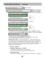
Page 43: ...2nd Stage Turnoff Point 3rd Stage Deadband Deadband Setpoint 3rd Stage Deadband 3rd Stage Timer 3rd Stage Turnoff Point 4th Stage Deadband Deadband Setpoint 4th Stage Deadband 4th Stage Timer 4th Stage Turnoff Point Free Cooling Free Cooling On Off Usable Outdoor Temp Mechanical Cooling Yes No Installation Settings Continued Min Heat Cool Difference Continued next page Settings ...

Page 44: ...d Disabled Aux Heat Lockout Temp Fan Off Delay Settings Heat Pump Lockout Enabled Disabled AUX Output Usage AUX Output Polarity Continued next page Sensor Settings Control Sensor Wired Sensor Use Calibrate Sensors Thermostat Sensor Only Wired Sensor Only Average Wired Thermostat Use as Outdoor Sensor Use as Remote Sensor Use as Supply Sensor Use as Return Sensor Thermostat Wired Sensor Humidity AU...

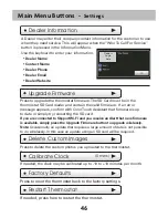
Page 45: ...s Dealer Information Dealer Name Contact Name Dealer Phone Dealer Email Dealer Website Calibrate Clock Factory Defaults Restart Thermostat Installation Settings Settings Test Outputs Upgrade Firmware Delete Custom Images Continued ...

Page 46: ...menu Name appears here General Setup Units F Fahrenheit F Celsius C SD Card Import and export files to and from the thermostat See the ColorTouch Assistant instructions for further details Import Settings from SD Card Export Settings to SD Card Upload files from ColorTouch Assistant or another thermostat Export files from one thermostat and import them into others Up to 14 characters NOTE A 2GB SD...

Page 47: ...me to adjust When used with a heat pump electric strip heat will be disabled while Smart Recovery is active Language en English Spanish Español French Français Menu Button Press for Cooling Press for Heat Press to turn Off Press to turn Fan On or Auto Cooler Button Warmer Button Single Setpoint Room Temperature When SimpleThermostat is on alerts will appear in the top bar of the main screen Press ...

Page 48: ...mpressor Min OFF Time 5m None 1 minute or 5 minutes At 6 cycles per hour the HVAC unit will only be allowed to energize once every 10 minutes The Cycles Per Hour limit may be overridden and reset by pressing the WARMER or COOLER buttons 2 3 4 5 6 No Limit Cycles Per Hour 6 Min Heat Cool Difference 2 The minimum gap between Heat and Cool setpoints 0 6 deg F Timers Deadbands Only available when dip ...

Page 49: ...s set to 2 degrees the room temperature will need to drop to 66 degrees before the heat turns on 3rd Stage Deadband 4th Stage Deadband 1st Stage Deadband 2 1 6 deg F 2nd Stage Deadband 2nd Stage Deadband 2 2nd Stage Timer 2mins 2nd Stage Turnoff Point Deadband Deadband or Setpoint Number of degrees past 1st stage before 2nd stage turns on 0 10 deg F Number of minutes past 1st stage before 2nd stag...

Page 50: ...ree Cooling outdoor air damper is closed Free Cooling Mechanical Cooling NO Mechanical Cooling YES If you don t have a compressor set Mechanical Cooling to NO Y1 will then be used to control the Free Cooling Damper s andY2 will be disabled If set to YES mechanical compressor cooling will be controlled by the Y2 terminal See page 53 for wiring diagram Installation Settings Damper1 Open Damper2 Clos...

Page 51: ...e the temperature for changeover to fossil fuel 5 60 deg F This feature is for heat pump applications only This will only appear if the GAS EL or HP dip switch is set for HP and the GAS or ELEC dip switch is set for Gas When Dual Fuel is ON an outdoor temperature or if Change With Outdoor is set to OFF a demand for third stage heat will be used to stop running the heat pump and switch to a fossil ...

Page 52: ...AUX output usage W3 IMPORTANT Aux Output Usage must be set for Hum or Dehum before any settings will take effect in the Humidity Main Menu AUX output polarity NO The AUX Output polarity may be set for Normally Open or Normally Closed to accommodate different types of humidification and dehumidification equipment Main Menu Buttons Settings ...

Page 53: ... are active Sensor Settings Control Sensor thermostat When a remote sensor is connected to the thermostat the user may choose which sensor source is used to measure room temperature Wired Sensor Use remote The wired sensor may be used as follows The integral humidity sensor may be calibrated 20 to 20 RH Calibrate Sensors 0 The thermostat and wired sensor may be calibrated 7 to 7 degrees F Thermost...

Page 54: ...rm with ColorTouch Assistant that firmware is up to date or simply try reinserting the SD card Dealer s Logo here Delete Custom Images Press to delete the custom photos you uploaded to the thermostat Dealer Name Contact Name Dealer Phone Dealer Email Dealer Website Calibrate Clock If needed the clock may be calibrated up to 10 to 10 minutes per month 0 mins Restart Thermostat If needed press here ...

Page 55: ...of your thermostat including the thermostat s ID Wi Fi Setup Choose your network from the list and enter the network password If your network does not appear in the list hit the refresh button Network Name 1 Network Name 2 Network Name 3 Network Name 4 BACK Local API OFF Enabling the local API allows 3rd party software to interface with your thermostat such as a home automation system ...

Page 56: ...port Account Skyport Skyport Services ON Weather Updates ON Pressing this button will let you know if you are paired with a Skyport account If not then you may follow prompt and instructions to create an account and add the thermostat to the account ...

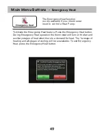
Page 57: ...ncy Heat operation the thermostat will turn on the fan and auxiliary stages of heat when there is a demand for heat The 1st stage of heating and all stages of cooling will be unavailable To exit Emergency Heat press the Emergency Heat button The Emergency Heat function is only available if your thermostat is set to control a Heat Pump ...

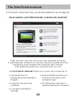
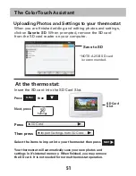
Page 58: ...o Venstar ColorTouch website in the background and updates the software and firmware the operating system for ColorTouch at no cost The ColorTouch Assistant allows you to use your computer to Upload photos for background and slideshow images Program a time period schedule Configure installation settings Upload dealer and service contact information and company logo An alternative method to update ...

Page 59: ...o SD SD Card Slot At the thermostat Press then Settings SD Card Insert the SD card into the SD Card Slot Next press Press Then press Select the items to import into your thermostat then press NEXT NOTE A 2GB SD card is recommended MENU Your thermostat will automatically save your new photos and settings in it s internal memory When finished you may remove the SD card It is not needed for normal th...

Page 60: ...ower to the Heating Air Conditioning system at the main fuse panel Most residential systems have a separate breaker for disconnecting power to the furnace Remove the cover of the old thermostat If it does not come off easily check for screws Loosen the screws holding the thermostat base or subbase to the wall and lift away Disconnect the wires from the old thermostat Tape the ends of the wires as ...

Page 61: ...iagrams that follow Wire from the Install on the old thermostat Function new thermostat terminal marked connector marked G or F Fan G Y1 Y Cooling Y1 W1 W Heating W1 0 B Rh R M Vr A Power R C Common C O B Rev Valve W1 O B W2 2nd Stage Heat W2 Y2 2nd Stage Cooling Y2 W3 3rd Stage Heat W3 OUT Outdoor Sensor SENSOR OUT Outdoor Sensor SENSOR O B is used if your system is a Heat Pump ...

Page 62: ...ection on page 53 If there are only 4 wires present that are connected to the existing thermostat there are at least 3 options available to connect the Venstar thermostat 1 Use the 4 wires as instructed in the Making 4 Wires Work When 5 Wires Are Required section on page 53 and note that the fan will only operate with a Heating or Cooling demand 2 Pull new thermostat wire from the HVAC equipment t...

Page 63: ...are at least 5 wires available 3 Purchase and install a Venstar Add A Wire accessory E If you have a heat pump with aux heat the Venstar model will require 6 wires R 24Vac C 24Vac W1 O B Reversing Value Y 1st Stage Compressor W2 Aux Heat and G Fan If you are short 1 wire there are at least 3 options available to connect the Venstar thermostat 1 Use the available wires as instructed in the Making 5...

Page 64: ...rminals that the wires are attached to 4 Remove the G wire from the terminal marked G 5 Place the G wire on terminal C 6 Place one end of the 3 long jumper on terminal G 7 Place the other end of the 3 long jumper on terminal Y Please note that there will be more than 1 wire on terminal Y 8 When connecting the wires to the Venstar thermostat note that the wire that was previously connected to the G...

Page 65: ...ocate the terminals that the wires are attached to 4 Remove the G wire from the terminal marked G 5 Place the G wire on terminal C 6 Place one end of the 3 long jumper on terminal G 7 Place the other end of the 3 long jumper on terminal Y Please note that there will be more than 1 wire on terminal Y 8 When connecting the wires to the Venstar thermostat note that the wire that was previously connec...

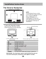
Page 66: ...both R 24 VAC Return and C 24 VAC Common be connected to the backplate terminals To remove the thermostat backplate Using the Finger Pull Areas pull the front housing away from the backplate Look for these tabs to locate the pull areas Pull out with thumbs in these areas Backplate Front Housing NOTE The backplate does not fully cover a full size vertical junction box The ACC WPLWH Venstar Wallplat...

Page 67: ...If O is chosen the W1 O B terminal will energize in cooling If B is chosen the W1 O B terminal will energize in heating 1 When GAS EL or HP is set for GAS EL This switch GAS or ELEC controls how the thermostat will control the Fan G terminal in heating mode When GAS is chosen the thermostat will not energize the Fan G terminal in heating When ELEC is chosen the thermostat will energize the fan in ...

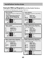
Page 68: ...ling with 1 stage Electric Heat 5 Wire 1 Stage Cooling 1 Stage Heat 24VAC Power 24VAC Common 1st Stage Heat 1st Stage Cool Fan Residential Commercial 2 Stage Cooling with 3 stage Gas Heat 8 Wire 2 Stage Cooling 3 Stage Heat 24VAC Power 24VAC Common 1st Stage Heat 2nd Stage Heat 3rd Stage Heat 1st Stage Cool 2nd Stage Cool Fan R C W1 O B Y1 G R C W1 O B Y1 G R C W1 O B W2 W3 AUX Y1 Y2 G 24VAC Power...

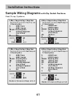
Page 69: ...or Heat Y2 2nd Stage Compressor Cool or Heat G Fan Residential Commercial Heat Pump with O ReversingValve 6 Wire 1 Stage Cooling 2 Stage Heat R 24VAC Power C 24VAC Common W1 O B Reversing Valve Y1 1st Stage Compressor Cool or Heat W2 Aux Heat G Fan Residential Commercial Heat Pump with O ReversingValve 7 Wire 2 Stage Cooling 3 Stage Heat R 24VAC Power C 24VAC Common W1 O B Reversing Valve W2 3rd S...

Page 70: ...K ohm sensor at 77F 25C NegativeTemperature Coefficient Residential Commercial Heat Pump with O ReversingValve and Fossil Fuel furnace 7 Wire 2 Stage Cooling 3 Stage Heat R 24VAC Power C 24VAC Common W1 O B Reversing Valve W2 3rd Stage Heat connected to furnace Y1 1st Stage Compressor Cool or Heat Y2 2nd Stage Compressor Cool or Heat G Fan Number of Compressor Stages set to 2 Dual Fuel set to On F...

Page 71: ...et point limit See Setpoint Limits page 28 SYMPTOM The heating does not attempt to turn on CAUSE The heating setpoint is set too low REMEDY Raise the heating setpoint or raise the heating set point limit See Setpoint Limits page 28 SYMPTOM When controlling a residential heat pump and asking for cooling the heat comes on CAUSE The thermostat reversing valve dip switch is set for B REMEDY Set the re...

Page 72: ... 1 Setting 6 Onelink Assistant 47 Compressor Lockout 37 Cool 1st stage deadband see Deadband 2nd stage deadband see Deadband Minutes of runtime 30 Custom Wallpaper 21 Cycles Per Hour 35 Daylight Savings 7 Deadband 1st stage 38 2nd stage 38 3rd stage 38 4th stage 38 Dealer Information 30 43 Delay Fan off see Fan Time between stages seeTime Delay Differential Heat and cool 37 Dimmer 18 Dip Switches ...

Page 73: ...nd stage deadband see Deadband electric strip heat see Aux Heat minutes of runtime 30 3rd stage deadband see Deadband 4th stage deadband see Deadband timer 38 turnoff point 38 electric heat pump 40 mode 4 program see Schedule runtime see Runtime setpoint 4 Heat Cool Indicator 21 Heat Pump aux heat 37 40 aux heat lockout 40 emergency heat 46 heat pump lockout 40 dip switch setting 56 multi stage 37...

Page 74: ... 8 Reset alert messages 16 thermostat settings see Factory Defaults runtime fan filter 15 UV light 15 Reversing Valve 50 Runtime resetting see Reset service filter 16 UV light 16 viewing 16 30 Schedule turn on off 8 view 8 edit 8 Screen Cleaning 19 Screensaver turn on off 14 setup 14 preview 14 SD Card 35 2nd stage turn off temperature 38 Security 28 Service alerts 15 information 15 29 Set Clock s...

Page 75: ...o 2nd stage 38 2nd stage to 3rd stage 38 3rd stage to 4th stage 38 Time schedule see Schedule Touch Calibration 19 Upgrade Firmware 43 User InterfaceThemes 21 UV Light resetting 16 runtime see Runtime setting see Runtime Vacation 24 modes 26 schedule 25 setpoints 26 W1 50 W2 50 W3 50 Wallpaper 21 Warranty 66 Wiring 50 dual fuel 56 free cooling 51 gas electric 56 heat pump 50 Y1 50 Y2 50 T U V W Y ...

Page 76: ... WHATSOEVER ALL WORK UNDERTHETERMS OFTHIS WARRANTY SHALL BE PERFORMED DURING NORMAL WORKING HOURS ALL REPLACEMENT PARTS WHETHER NEW OR REMANUFACTURED ASSUME ASTHEIR WARRANTY PERIOD ONLYTHE REMAININGTIME PERIOD OFTHIS WARRANTY THE MANUFACTURER WILL NOT BE RESPONSIBLE FOR 1 Normal maintenance as outlined in the installation and servicing instructions or owner s manual including filter cleaning and o...

Page 77: ...Printed on recycled paper P N 88 1088 Rev 1 03 15 Patents Issued Pending ...

Reviews: