background image

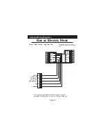
Sample Wiring Diagrams

Gas or Electric Heat

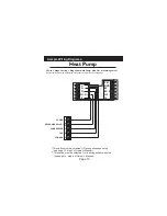
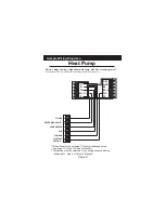
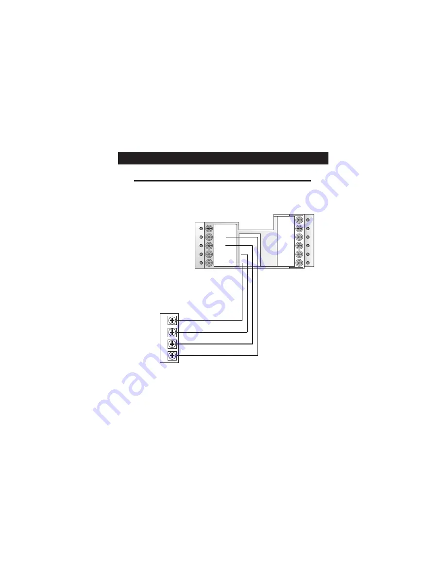
4 Wire, 1 Stage Cooling, 1 Stage Gas Heat

Residential Gas or Electric Heat*, 
Electric Cool, split systems & package
units
    

CK1
GND
RS
RS+5
W2
Y2

 C
 G
 Y1
W1-O-B
 R

POWER

R

COMPRESSOR

Y

W

GAS VALVE

or

STRIP HEAT

FAN

G

*

 If using first stage electric heat, this option must be 

  selected ON (see page 13, step 5 of Owner’s Manual).

Page 6

Summary of Contents for T1100FS

Page 1: ...For All Works with Virtually All Equipment Non Volatile memory Keypad lockout Single or Dual setpoint with Adjustable Deadband O or B Terminal Optional Outdoor Sensor Programmable Fan Mounts Flush wit...

Page 2: ...ER TO THE HEATER AIR CONDITIONER BEFORE REMOVING THE OLD THERMOSTAT AND INSTALLING THE NEW THERMOSTAT WARNING This device complies with Part 15 of the FCC rules Operation is subject to the following t...

Page 3: ...river Wire cutter Stripper Make sure your Heater Air Conditioner is working properly before beginning installation of the thermostat Carefully unpack the thermostat Save the screws wall anchors and in...

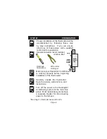
Page 4: ...terminal for easy reconnection to the new thermostat STEP 2 REMOVE REPLACE OLD THERMOSTAT Keep the old thermostat for reference purposes until your new thermostat is functioning properly Remove the w...

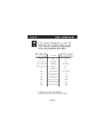
Page 5: ...l systems O B is used if your system is a Heat Pump Wire from the old thermostat terminal marked Function Install on the new thermos tat connector marked G or F Fan G Y1 Y or C Cooling Y1 W1 W or H He...

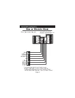
Page 6: ...d ON see page 13 step 5 of Owner s Manual Gas or Electric Heat 5 Wire 1 Stage Cooling 1 Stage Gas Heat Residential Gas or Electric Heat Electric Cool split systems package units CK1 GND RS RS 5 W2 Y2...

Page 7: ...eat Residential Gas or Electric Heat Electric Cool split systems package units CK1 GND RS RS 5 W2 Y2 C G Y1 W1 O B R POWER R COMPRESSOR Y W GAS VALVE or STRIP HEAT FAN G If using first stage electric...

Page 8: ...sidential two stage cooling with Gas or Electric Heat CK1 GND RS RS 5 W2 Y2 C G Y1 W1 O B R POWER R COMPRESSOR Y W GAS VALVE or STRIP HEAT COMMON C FAN G 2nd STAGE COOLING Y2 If using first stage elec...

Page 9: ...commercial 1 Stage Cooling with 2 Stage Gas or Electric Heat CK1 GND RS RS 5 W2 Y2 C G Y1 W1 O B R POWER R COMPRESSOR Y W GAS VALVE or STRIP HEAT COMMON C FAN G 2nd STAGE HEATING W2 If using first sta...

Page 10: ...tage Heat CK1 GND RS RS 5 W2 Y2 C G Y1 W1 O B R POWER R COMPRESSOR Y W GAS VALVE or STRIP HEAT COMMON C FAN G 2nd STAGE HEATING W2 selected ON see page 13 step 5 of Owner s Manual Commercial heat pump...

Page 11: ...selected O or b during advanced setup see page 13 step 4 of Owner s Manual Heat Pump CK1 GND RS RS 5 W2 Y2 C G Y1 W1 O B R POWER R COMPRESSOR Y O b REVERSING VALVE COMMON C FAN G 5 Wire 1 Stage Coolin...

Page 12: ...ooling 2 Stage Heat Heat Pump with O or b reversing valve Residential Heat Pumps split systems package units with auxiliary heat 2nd STAGE HEATING W2 This option must be selected ON during advanced se...

Page 13: ...play Press the UP or DOWN buttons until the set temperature is 10 degrees below room temperature The HVAC unit should Turn the power on to the Heating Air Conditioning system energize in the cooling m...

Page 14: ...below TROUBLESHOOTING SYMPTOM The air conditioning does not attempt to turn on CAUSE The compressor timer lockout may prevent the air conditioner from turning on for a period of time REMEDY See page 1...

Page 15: ...t pump operation TROUBLESHOOTING SYMPTOM When calling for cooling both the heat and cool come on CAUSE The thermostat is configured to control a heat pump and the HVAC system is a conventional non hea...

Reviews: