background image

12

Air Patrol

Air Patrol continually samples the Indoor Air Quality (IAQ) at the thermostat.

When Air Patrol is enabled and the Indoor Air Quality drops into the selected 

category:

•   The fan will turn on to circulate the air through the HVAC’s filtration 

system with a 5 minute minimum runtime

•   The fan will continue to operate until:

-   The Indoor Air Quality improves, OR

-   The fan runtime reaches its selected maximum runtime per hour,  

the Air Patrol Duration

•  Additionally, the thermostat’s AUX output can be asserted to control  

3rd party devices such as ionizers or extra filtration*

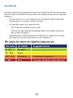
The values for Indoor Air Quality categories are:

IAQ Index  Air Quality 

Suggested Action

0 - 50 

Excellent

51 - 100 

Good

101 - 250 

Moderate 

Ventilation suggested

> 250 

Poor 

Increase ventilation with clean air

Summary of Contents for T4975-IAQ

Page 1: ...DIGITAL THERMOSTAT IAQ Owner s Manual and Installation Instructions Up to 2 Heat 4 Cool Stages With Air Patrol Humidity Control Light Activation COMMERCIAL T4975 IAQ...

Page 2: ...void the user s authority to operate the equipment This equipment has been tested and found to comply with the limits for a Class B digital device pursuant to Part 15 of the FCC Rules These limits are...

Page 3: ...y interference including interference that may cause undesired operation of the device L metteur r cepteur exempt de licence contenu dans le pr sent appareil est conforme aux CNR d Innovation Sciences...

Page 4: ...dule ON OFF 10 Programming a Schedule 10 AIR PATROL 12 VENNET SENSORS 15 Pairing a sensor 15 Un pairing a sensor 16 Factory Defaulting a sensor 16 SETUP STEPS Program Mode non programmable or 7 day pr...

Page 5: ...ff 32 Local API on off 32 Show Clock 32 Show IAQ 32 Clear all messages 32 LOCKING UNLOCKING THE BUTTONS 33 HOLIDAY 34 CALIBRATION 35 RESTORING FACTORY DEFAULT SETTINGS 36 TEST OUTPUTS AND CALIBRATE TE...

Page 6: ...the amount of moisture in the air Icon The word or symbol that appears on the thermostat display Mode The current operating condition of the thermostat i e Off Heat Cool Auto Non ProgrammableThermost...

Page 7: ...2 Backlit Scrolling Display Backlit Cooler Warmer Buttons Backlit LCD Display Override Button Heat or Cool Demand Indicator Red Heat Green Cool Setup Buttons Behind Door Get To Know Your Thermostat...

Page 8: ...3 Setup Buttons Get To Know Your Thermostat...

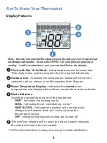
Page 9: ...Temperature Display Indicates the current room temperature and displays the outdoor temperature when selected 4 Mode Indicators Selects the operational mode of the equipment HEAT Indicates the heating...

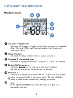
Page 10: ...red SetTemperature Indicates desired room temperature s Also displays the highest and lowest temperatures for the day 10 Wi Fi icons One dot will always be present and the full wifi icon will appear w...

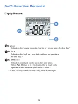
Page 11: ...d outdoor temperature for the day 14 Fan On icon Indicates constant continuous fan operation When Fan On is not lit indicates the fan will only operate when necessary to heat or to cool Hi and LoTempe...

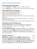
Page 12: ...s in Heat or Cool mode will adjust only the heat or cool setpoints individually displayed AUTO CHANGEOVER MODE Pressing the WARMER or COOLER buttons in Auto mode will adjust both the heat and cool set...

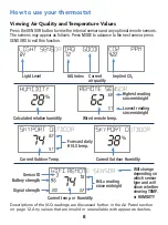
Page 13: ...in the Air Patrol section on page 12 Any values that are invalid or unavailable with appear as dashes IAQ index Calculated relative humidity Wired remote temp Highest reading since midnight Lowest rea...

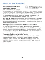
Page 14: ...perate as described above Viewing only connected wifi or VenNet Sensor Values You may also view connected wifi and VenNet sensor values after pressing ACCESSORY STATUS followed by COOLER button Use MO...

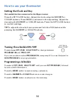
Page 15: ...ering a schedule Press the WARMER or COOLER buttons to make changes Press the MODE button to advance to the next step OFF RUN HOLD TO SET OFF RUN HOLD TO SET Setting the Clock and Day Not available wh...

Page 16: ...ccupied time periods in a day Select the Mode for the Occupied period Press the Warmer or Cooler buttons to choose the mode for the occupied period Adjust the Occupied Cool Setpoint Press the Warmer o...

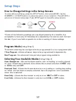
Page 17: ...me The fan will continue to operate until The Indoor Air Quality improves OR The fan runtime reaches its selected maximum runtime per hour the Air Patrol Duration Additionally the thermostat s AUX out...

Page 18: ...orner 1 2 Select Settings at the bottom of the drop down menu 3 Select Indoor Air Quality in the shaded area of Settings Setup Configuration Air Patrol is configured from Skyweb Venstar s Skyport web...

Page 19: ...output 6 Set the Air Patrol Duration This is the maximum the fan is allowed to run per hour If the Air Quality does not reach the next better IAQ level in this allotted time it will stop the fan and...

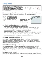
Page 20: ...age from the display and stop the pairing procedure on the thermostat 4 Once pairing is completed you must select the type of sensor Remote or Outdoor a At this point the thermostat will display REMOT...

Page 21: ...It is advisable to name the sensor before pairing additional sensors Returning a Sensor to Factory Default settings If you are pairing the sensor to a new thermostat you will need to remove the previ...

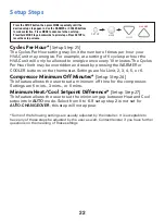
Page 22: ...n manually selected Auto Changeover is not available when this is selected Heat Only Allows the thermostat to only turn on HEAT or OFF modes Cool Only Allows the thermostat to only turn on COOL or OFF...

Page 23: ...OLER MODE SETUP Night Dimmer Brightness Setup Step 6 Off through seven levels of brightness Night Dimmer Start Time Setup Step 7 12 00 am to 12 00 am Night Dimmer Stop Time Setup Step 8 12 00 am to 12...

Page 24: ...rent Override Hours Setup Step 14 This counter keeps track of the number of hours that the thermostat is overridden into Occupied settings Press FAN to reset Current UV Lamp Calendar Days Setup Step 1...

Page 25: ...FF is displayed to disable this feature UV Lamp Runtime Setup Step 19 Set UV Lamp Calendar Days Setup Step 19 This timer allows the user to specify the number of calendar days the UV Lamp will operate...

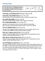
Page 26: ...oint Setup Step 23 35 99 Minimum Cool Setpoint Setup Step 24 35 99 Setup Steps Press the SETUP button then press MODE repeatedly until the desired setup step appears Use the WARMER or COOLER buttons t...

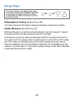
Page 27: ...ns Minimum Heat Cool Setpoint Difference Setup Step 27 This feature allows the user to set the minimum gap between Heat and Cool setpoints in AUTO mode Select from 0 to 6 If setup step 2 is not set fo...

Page 28: ...1 Specifies the additional minimum temperature difference after the third stage turns on before the final stage of cooling is activated 0 10 Minutes Between 1st and 2nd Stage Setup Step 32 Specifies t...

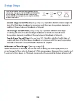
Page 29: ...g will turn off at third stage deadband or remain on until the room temperature demand is satisfied Choose between Deadband or Setpoint Minutes of Fan Purge setup step 38 When this feature is activate...

Page 30: ...Wired Remote averages internal and attached wired remote sensor Average all Sensors averages internal any attached wired or paired wireless sensors These options only appear if step 39 Wired Sensor Ty...

Page 31: ...ng will run to satisfy a Cool to Dehumidify demand 0 20 Max Unocc Dehum Overcool Setup Step 47 Specifies how many degrees below the Cool setpoint the air conditioning will run to satisfy a Cool to Deh...

Page 32: ...is set for 6am at 72 F heating and 75 F cooling the thermostat will turn the system on before 6am in an effort to bring the temperature to its correct setting at exactly 6am The thermostat learns from...

Page 33: ...f OCCUPIED is selected when the dry contact is active the thermostat will be forced into the programmed occupied mode setpoints and the occupied icon will blink This setting is useful for allowing a t...

Page 34: ...eens WARMER COOLER MODE SETUP Setup Steps Light Activation Sensitivity Setup Step 56 With the lights on in the space press the FAN button to set the sensitivity of the light sensor This light level wi...

Page 35: ...repeatedly until the desired setup step appears Use the WARMER or COOLER buttons to make selection Press MODE to advance to the next step Press hold MODE to go backwards to prior steps Press SETUP to...

Page 36: ...received from the utility Since you might be paying more for energy while an event is active you can impose tighter limits on setpoint ranges that are only enforced during the event Static Cool Setpo...

Page 37: ...LED Air Patrol Fan on Minutes Setup Step 68 When IAQ value meets the level specified in Step 67 the indoor blower will run for the length of time specified in this step 5 to 60 minutes This step only...

Page 38: ...ER and COOLER buttons together for 5 seconds The icon will appear on the display then release the buttons Press all three buttons in the order outlined above for button lockout To unlock the buttons p...

Page 39: ...iday setup programming at the local thermostat is not allowed In this case Holiday setup and programming is accomplished with the Skyport Web App Skyport gives the user extensive control over Holiday...

Page 40: ...ENSORS UP YES MODE NEXT appears on the display 3 Press UP WARMER to move to thermostat screen then adjust the indicated room temperature readings as desired then MODE to store and move to next screen...

Page 41: ...nd or reset to factory settings Press hold FAN for 2 seconds to bring defaults into your selection After successfully defaulted the screen will return to all icons Press SETUP to return to normal ther...

Page 42: ...ling display will read NOTHING ON Next Press WARMER to turn on and cycle up through the heating stages Press COOLER to turn the heating stages off Press MODE to exit Press COOLER to turn on and cycle...

Page 43: ...Heating Air Conditioning system at the main fuse panel Most residential systems have a separate breaker for disconnecting power to the furnace Remove the cover of the old thermostat If it does not com...

Page 44: ...follow Wire from the Install on the old thermostat Function new thermostat terminal marked connector marked G or F Fan G Y1 Y Cooling Y1 W1 W Heating W1 Rh R M Vr A Power R C Common C W2 2nd Stage Hea...

Page 45: ...SENSOR connections REMOTE Remote sensor SENSOR connections DRY Dry Contact CONTACT connections IMPORTANT This thermostat requires both R 24VAC Return and C 24VAC Common be connected to the backplate t...

Page 46: ...ctions 1 This switch GAS or ELEC controls how the thermostat will control the Fan G terminal in heating mode When GAS is chosen the thermostat will not energize the Fan G terminal in heating When ELEC...

Page 47: ...EMOTE SENSOR OUTDOOR SENSOR C R Y4 Y3 Y2 Y1 W2 W1 G 24 VAC Power COOLING STAGES HEATING STAGES FAN Wiring Diagram Installation Instructions Set GAS ELEC dip switch to ELEC position to have fan turn on...

Page 48: ...y Contact and Aux Output G Y1 Y2 W3 R W1 O B W2 HUM DEHUM C AUX REMOTE SENSOR DRY CONTACT OUTDOOR SENSOR 24V is present between these two terminals whenever the air quality is at worse than the specif...

Page 49: ...old for 10 seconds All icons appear Press MODE to advance through the setup steps Press WARMER or COOLER to adjust the selection WARMER COOLER MODE SETUP HI Lo Program ONOFF Outdoor Fan On COOL AUXHEA...

Page 50: ...ac between R C SYMPTOM The air conditioning does not attempt to turn on CAUSE The cooling setpoint is set too high REMEDY Lower the cooling setpoint or lower the cooling set point limit See Setpoint L...

Page 51: ...Runtime Hours 19 0 1999 Hours 0 12 Current Aux Heat Runtime Hours 19 0 1999 Hours 0 13 Current Cool Runtime Hours 19 0 1999 Hours 0 14 Current Override Hours 19 0 1999 Hours 0 15 Current UV Lamp Calen...

Page 52: ...Remotes Average Thermostat and Wired Remote Average All Sensors Option only if prior step Remote Thermostat 41 Wireless Remote to Use 25 list of wifi sensors currently linked to thermostat This step...

Page 53: ...point 31 65 90 90 61 Event Min Heat Setpoint 31 50 85 50 62 Static Cool Setpoint 31 65 85 82 63 Static Heat Setpoint 31 65 85 60 64 Cool Setpoint Offset 31 1 to 15 4 65 Heat Setpoint Offset 31 1 to 15...

Page 54: ...WHATSOEVER ALL WORK UNDERTHETERMS OFTHIS WARRANTY SHALL BE PERFORMED DURING NORMAL WORKING HOURS ALL REPLACEMENT PARTS WHETHER NEW OR REMANUFACTURED ASSUME ASTHEIR WARRANTY PERIOD ONLYTHE REMAININGTIM...

Page 55: ...P N 88 1449 Rev 2 01 18 22 Patent Pending...

Reviews: