11
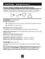
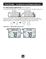
Installation Instructions
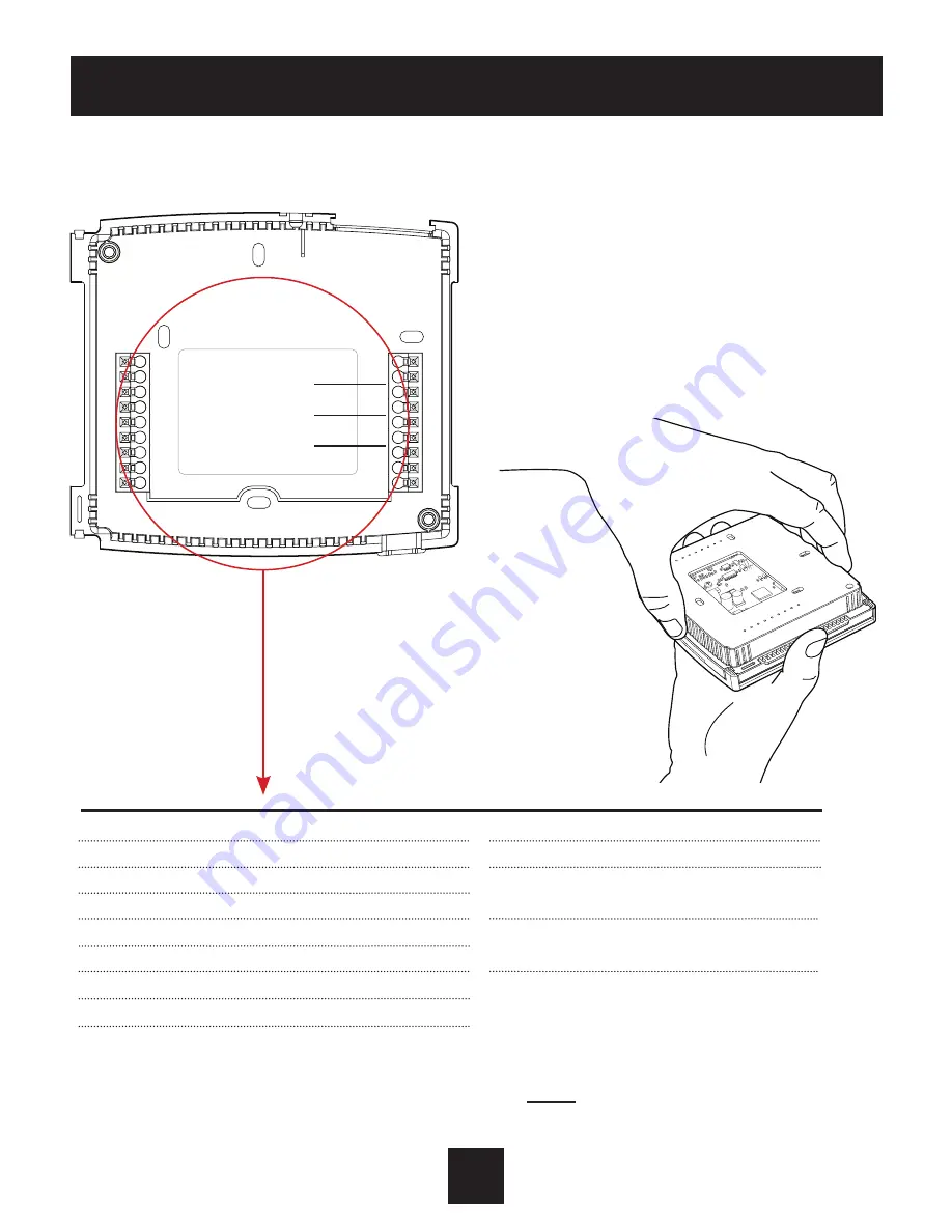
DRY
CONTACT
G
Y1
Y2
W3
R
W1/O/B
W2
HUM
DEHUM
C
AUX
REMOTE
SENSOR
OUTDOOR
SENSOR
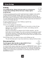
The Voyager Thermostat Backplate
R
24 VAC return
G
Fan relay
W1/O/B
1st stage heat circuit
W2
2nd stage heat circuit
Y1
1st stage compressor relay
Y2
2nd stage compressor relay
W3
3rd stage heat circuit
HUM
Humidifier control circuit
DEHUM
Dehumidifier control circuit
C
24 VAC common
AUX
Aux output
OUTDOOR Outdoor sensor
SENSOR connections
REMOTE
Remote sensor
SENSOR connections
DRY
Dry Contact
CONTACT connections
IMPORTANT: This thermostat requires both R (24 VAC Return) and
C (24 VAC Common) be connected to the backplate terminals.
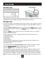
To remove the thermostat backplate:
Gently separate the display from
the base by pulling first from one
side, then the other until the two
pieces unsnap. A small screwdriver
may be used, very carefully, to start
seperating the two pieces.

