5
INSTALLATION
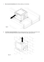
Position the unit, taking into consideration the position of the rooms to be ventilated, the exhaust position
and the electrical services. Ensure there is adequate access for installation and maintenance. The unit can
be mounted horizontally or vertically. It can be positioned on the floor, wall or ceiling.
If the unit is sited in the heated void of the dwelling a condensate drain should not be necessary.
When sited in a cold void, consideration should be given to fitment of a condensate drain. Alternatively the
unit and ducting can be externally insulated to minimize condensation within the units housing.
To reduce the system resistance in your duct system, and thereby avoid an increase in speed, power
consumption and sound of the fan, follow these guidelines:
1.1. Keep the length of duct runs to a minimum, particularly the exhaust duct run.
1.2. If you need to use flexible ducting, make sure that it is fully extended and not crushed,
sagging or torn.
1.3. Try to minimize the systems pressure drop by designing for lower in-duct velocities and connect to
the rooms with low pressure drop ceiling valves.
1.4. The bend radius (measured to the inside of the bend), should be at least 1x the duct diameter.
1.5. Avoid having any bends, filters or other obstructions within 250mm of the fan inlets and outlet.
1.6. Set the valves to their maximally opened positions for a minimal pressure drop.
Securely mount the unit through the mounting holes on the casing using appropriate fixings for the
mounting substrate. Anti-vibration mounts; acoustic mat or rubber bushes can also be used.
Fixings (not supplied) must be capable of securing 4 x the weight of the unit. Unit weight: 4.1kg
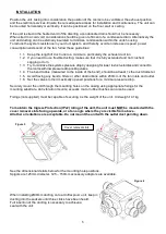
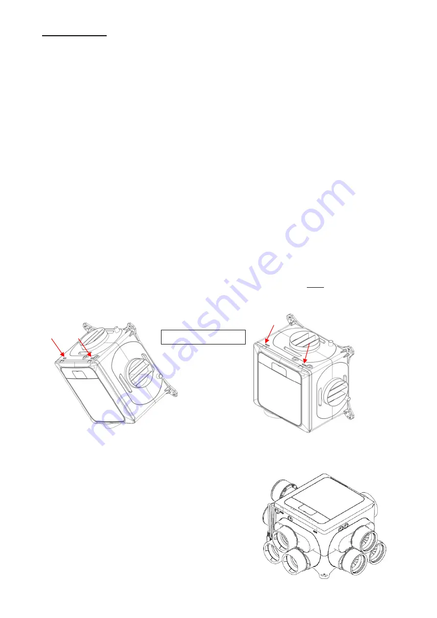
To maintain the Ingress Protection (IPx2) rating of the unit, the unit must NOT be mounted with the
cover removal slots facing upwards, or at an angle where they are visible from above.
All other orientations are acceptable. Do not mount the unit with the outlet duct pointing down.
See the dimensional details below for the mounting hole positions.
Spigots are 125mm diameter. 125
– 150mm accessory adaptors are available.
When installing Ø90mm ducting onto a Unif unit, keep inserting the
ducting into the sockets until three clicks have been heard.
Full insertion of the ducting is necessary to achieve a
seal with the unit.
Cover removal slots.
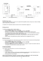
Figure 3
Figure 4
Summary of Contents for 1003000074
Page 6: ...6 Figure 5 Figure 6...
Page 26: ...26 Figure 7...
Page 36: ...36 Batterie Commutateur vitesse 4 voies 230 V...


