background image


2.0   Site Requirement


2.1 

Information


1. The unit must be sited and connected by a 
suitably competent person and be in accordance 
with current UK Building Regulations and I.E.E. 
Wiring Regulations (BS 7671).


2. The unit is intended for permanent connection 
to the mains electrical supply.


3. Wiring to the unit in the UK must be via a 
switched fused spur. The switched fused spur 
must have a 3mm minimum contact gap in all 
poles.


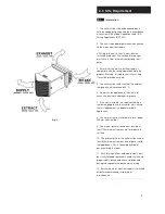
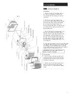
Fig. 2


4. Ensure that the mains electrical supply is 
compatible with the rating label attached to the 
product. Warning: this appliance is class 1 and 
it must therefore be earthed.


5. The unit must be sited such that the ambient 
temperature will not exceed 40° C.


6. Do not site the appliance in the vicinity of 
excessive levels of airborne oil or grease.


7. If the unit is installed in a room containing a 
fuel burning appliance, the installer must ensure 
that air replacement is adequate for both 
appliances.


8. The unit must not be installed at a level below


500mm from the floor.


9. The internal grille surround must be sited at 
least 125mm away from any wall or projecting 
surface.


10. The external grille of the unit must be sited at 
least 600mm away from any flue of gas or solid 
fuel appliances. This is to avoid back flow of 
gases entering the room.


11. All safety regulations and requirements must 
be strictly followed to prevent hazards to life and 
property both during and after installation and 
during subsequent maintenance or servicing.


12. Ensure the mains electrical supply is switched 
off before commencing installation or 
maintenance.


                                                                         5 

Summary of Contents for 14120020

Page 1: ...K Through the wall Heat Recovery Ventilator Installation and Maintenance Instructions PLEASE READ INSTRUCTIONS IN CONJUNCTION WITH ILLUSTRATIONS PLEASE SAVE THESE INSTRUCTIONS Stock Ref No HR200WK 141...

Page 2: ...should be provided with a local isolator switch fitted with a 3A fuse capable of disconnecting all poles and having a contact separation of at least 3mm 5 These units must be earthed 6 Precautions mu...

Page 3: ...and maintenance 3 Certain applications may require the installation of sound attenuation to achieve the sound levels required 4 The unit must not be connected directly to a tumble drier 5 The supply...

Page 4: ...low This provides up to 75 heat recovery from the stale extracted air 3 The power consumption for the unit is 20W trickle speed 60W normal speed and 130W boost speed 4 The three selectable speeds prov...

Page 5: ...Do not site the appliance in the vicinity of excessive levels of airborne oil or grease 7 If the unit is installed in a room containing a fuel burning appliance the installer must ensure that air rep...

Page 6: ...l control arrangement for the HR200WK unit above 2 After considering the site requirements Section 2 0 select a suitable site for the unit and controllers and work out the cable runs WARNING Before de...

Page 7: ...the top right hand side of the housing Note for the purpose of condensation drainage a prop is fitted to the underside of the housing to cause it to adopt a downwards tilt to the outside wall 4 Fix th...

Page 8: ...nductors of the cable to the appropriate terminals in accordance with the appropriate wiring diagram Fig 5 6 7 8 9 NOTE Refer to the fitting and wiring instructions provided with the controller used T...

Page 9: ...4 0 Electrical Fig 9 Fig 8...

Page 10: ...the grille surround after unscrewing its retaining screws Slide out the heat exchanger 7 Wash the grille filter and heat exchanger in warm water using a mild detergent and dry thoroughly CAUTION Keep...

Page 11: ...4 months Clean cell replace filters the new filters will be supplied with 4 additional Timestrip indicators Note The above is the minimum requirement more frequent cleaning intervals may be needed dep...

Page 12: ...l Demand Control Declared Max Internal External Leakage Rates for BVUs or carry over for regenerative heat exchangers only Ext Leakage Rates for Ducted UVUs 5 Internal 5 External Mixing Rate of Non Du...

Page 13: ...Notes...

Page 14: ......

Page 15: ......

Page 16: ...to misuse neglect or damage Has not been modified or repaired by any person not authorised by the company IF CLAIMING UNDER TERMS OF GUARANTEE Please return the complete product carriage paid to your...

Reviews: