background image

2


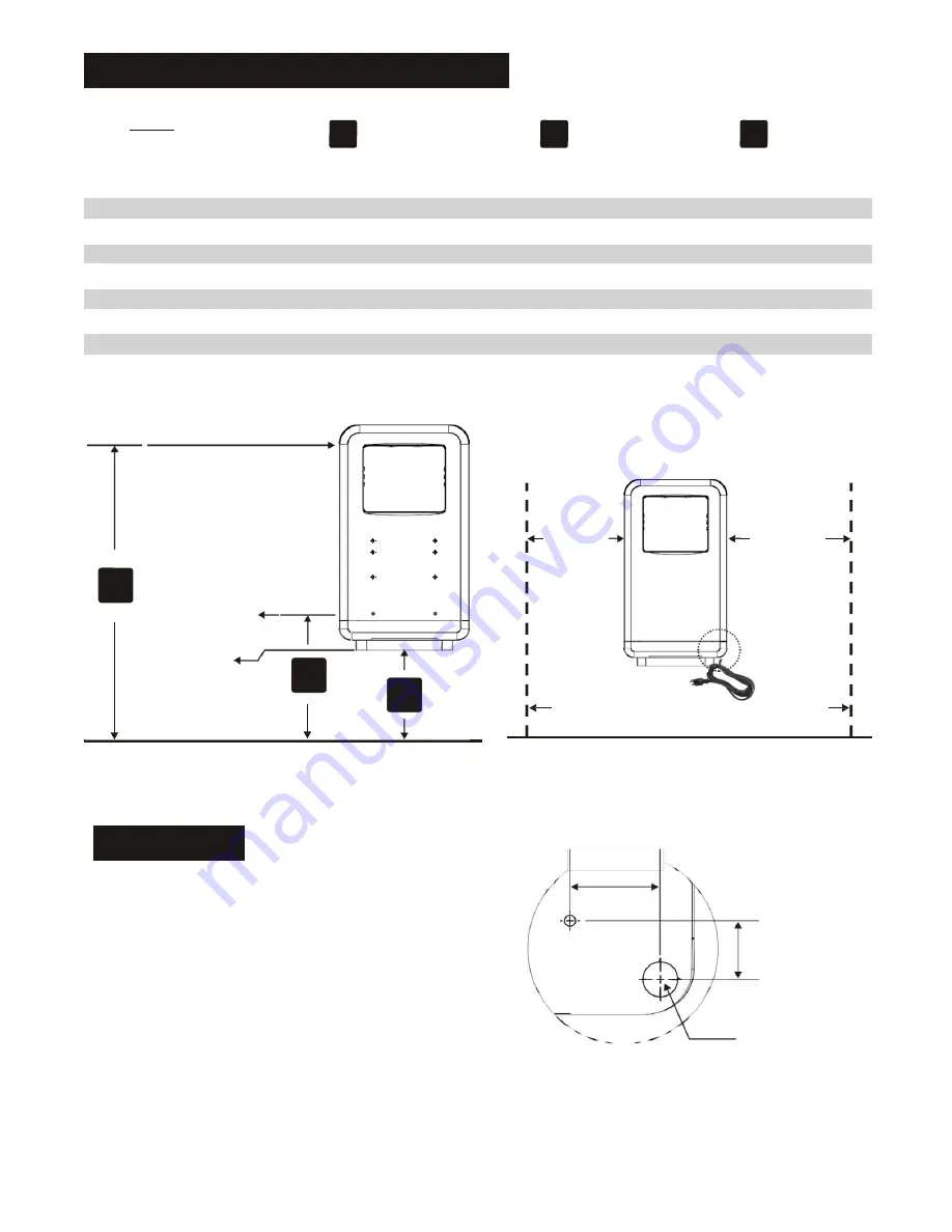
Recommended Mounting Heights


DIM’S


mm


A


From Top of Hand


Drying  Chamber


B  

C


From Datum Point  

From Bottom of Dryer


    Men  

1150      

710      

622     


Women


1080


640


552


    Children 4-7 years  

780  


340      

252     


Children 8-10 years


880


440


352


    Children 11-13 years  

965  


525      

437     


Children 14-16 years


1080


640


552


    Handicaped  

900  


460      

372     


Top of Hand


Drying  Chamber


A


Datum  Point


Bottom  of


Dryer  

B


C


45cm 


55cm 


A


Floor


Power Cord Reach Range


Floor  


Cable entry 


57.5 


The dryer is supplied with a power cord. The power cord 

entry position is in the rear, right side bottom of dryer. The 

length of the power cord is 1.5M.  


Datum  point


37 


Ø22  (Ø7/8)  
 
 
Cable entry  
Position.             


Detail A Unit Rear


Summary of Contents for 403368

Page 1: ...1 2 kW High Speed Hand Dryer Model No 403368 220 240V 50Hz Operating Instructions Please read instructions in conjunction with the illustrations Please save these instructions...

Page 2: ...ANCE DATA 220 240Vac 50 60 Hz 4 6 5A 1 0 1 2 kW 65 100 m s 140 224 mi hr Adjustable 45 C 113 F Ambient Temp 20 C 68 F 89 124 m h 55 76 CFM 3 0 mm thick molded ABS plast c 1HP 400 750W 11000 20000 R P...

Page 3: ...ren 11 13 years 965 525 437 Children 14 16 years 1080 640 552 Handicaped 900 460 372 Top of Hand Drying Chamber A Datum Point Bottom of Dryer B C 45cm 55cm A Floor Power Cord Reach Range Floor Cable e...

Page 4: ...should be supervised to ensure that they do not play with the appliance Installation Steps 1 Tape the installation template to the appropriate location on the mounting surface Drill eight 8 holes at m...

Page 5: ...leaning solution Do not Soak Do not hose down Never use abrasives to clean the cover Caustic chemicals may damage unit finish No internal parts need any regular cleaning Circuit Diagram L N G Y Red 11...

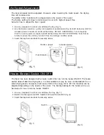
Page 6: ...er the unit may not start if low line Voltage condition exists 3 Insert the tray back and lock the security screw Reduce power Increase power Potentiometer OFF ON Reduce fig 1 fig 2 Heater Element Swi...

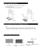
Page 7: ...3 Insert the tray back and lock the security screw Recommended Period for Changing the filter Filter In general use normal light usage it s recommended to change the filter six 6 months In dusty dirt...

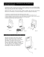
Page 8: ...e key to loosen the security screw of the base plate and remove the machine fig 2 3 Use a screwdriver to loosen the screw 2 pcs on the ceramic and replace it with a new one fig 3 4 Put the machine bac...

Page 9: ...spares please contact your supplier for details 403371A Supplied by APL 1012 This product should not be disposed of with household waste Please recycle where facilities exist Check with your local au...

Reviews: