background image


10


G:6 

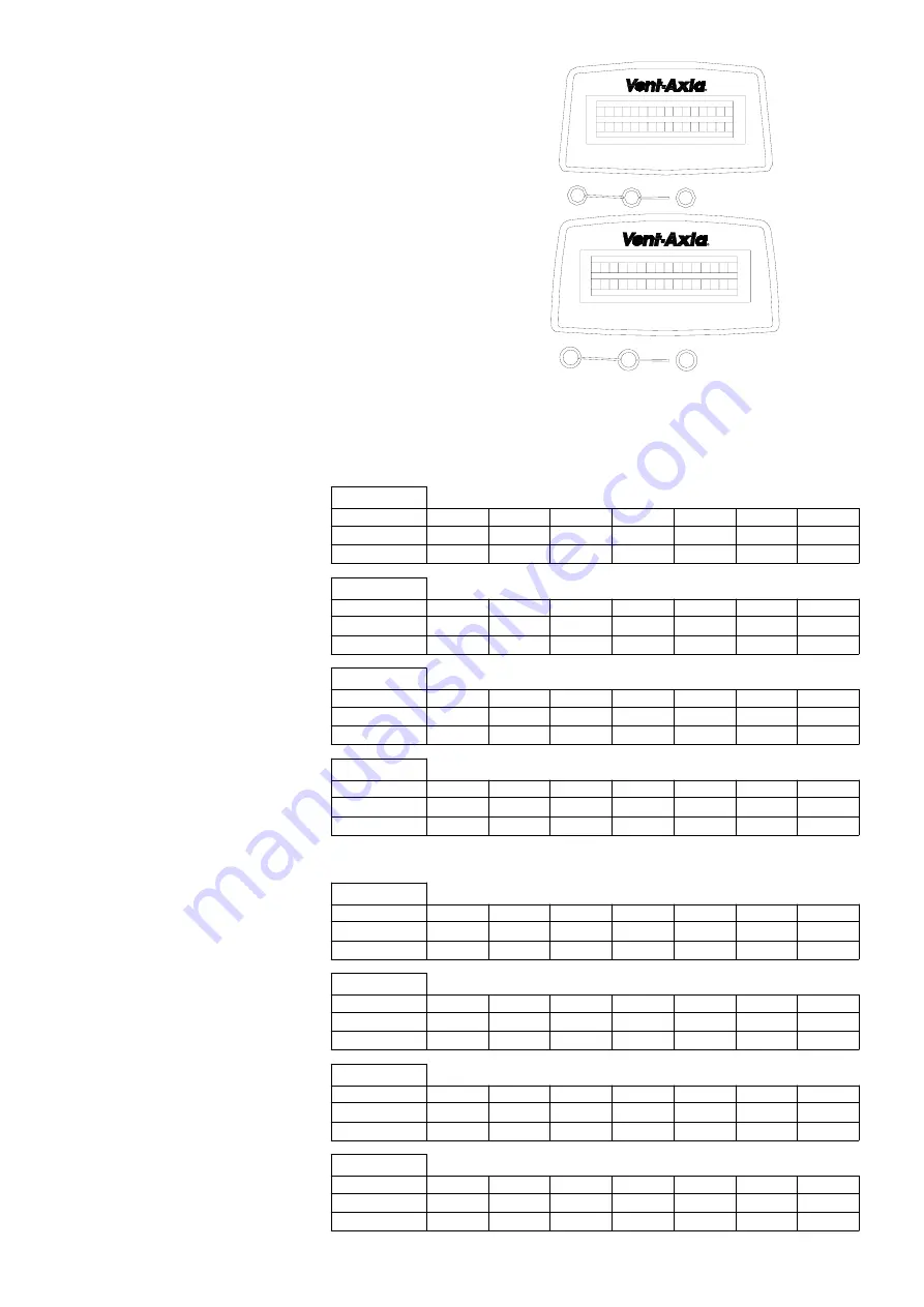
Adjusting the Medium Airflow Rates 


Press the


“ V ” “

Λ

 ” and `set’ Keys for more than  

5 seconds until the display changes  
to the screen opposite. 
 
Press the “

Λ

 ” until the display  

changes to the screen opposite. 
 
The present rate number for each is shown.  
Press `SET’ to adjust intake rate,  
`SET’ again for Exhaust rate and SET again to  
store the new values. 


The external pressure head available is a minimum of 200Pa at all speeds.  However, the higher the 
resistance of the system the higher will be the power that is consumed.  Take care to design, install and 
commission the system with the least resistance in order to minimise power consumption. 
The figures quoted are nominal air flows which are subject to the design, installation and commissioning of the 
complete ventilation system.  The medium and boost inlet and extract flows can be adjusted independently via 
the controller as described in the Fitting and Wiring information. 
 

Air Minder Plus 290


rate numbers and corresponding 
Airflow rates, Nominal setting 
shown bold 


Air Minder Plus 375


rate numbers and corresponding 
Airflow rates, Nominal setting 
shown bold 


Press the Boost Button 

*


for 12 seconds to reset to  
factory default setting. 


v

v

SET

R u n n i n g

T i m e

0 0 0 2 0

v

v

SET

I n t a k e

E x h a

0 8

u s t

0 8

M

M

House size 1
Low

   1    60

Medium

   2    70    3     80   4      90 

 5    120 

  6     140  7    160   8    180

Boost

   9    200

House size 2
Low

   2    70

Medium

  3    80    4     90    5    120 

6    140 


  7     160  8    180   9    200

Boost

  10   230

House size 3
Low

   3    80

Medium

  4    90    5    120   6    140 

7    160 

  8     180  9    200  10   230

Boost

  11   270

House size 4
Low

   4     90

Medium

  5    120  6    140  7     160 

8    180 

  9     200  10   230 11   270

Boost

  12   290

House size 1
Low

   1    90

Medium

  2    100  3    120   4    135 

 5   180 

  6   210  7    240   8    270

Boost

   9    290

House size 2
Low

   2    100

Medium

   3    120  4    135   5   180 

6    210 

  7   240  8    270   9    290

Boost

  10   330

House size 3
Low

   3    120

Medium

   4    135  5    180   6   210 

7    240 

  8    270  9    290  10  330

Boost

  11   360

House size 4
Low

   4    135

Medium

   5    180  6    210  7    240 

8    270 

  9   290  10   330  11   360

Boost

  12   380

Summary of Contents for Air Minder Plus

Page 1: ...ABC WHOLE HOUSE HEAT RECOVERY UNIT Installation Connection and set up Instructions READ INSTRUCTIONS IN CONJUNCTION WITH ILLUSTRATIONS PLEASE SAVE THESE INSTRUCTIONS...

Page 2: ...applications may require the installation of sound attenuation to achieve the sound levels required The unit must not be connected directly to a Cooker Hood or Tumble Dryer The Condensate Waste pipe...

Page 3: ...ONTROLLER Carton 2 8 TWO FAN BLOWER UNITS 9 TWO INLETS CARTON 2 ITEM 8 2 off ITEM 9 2 off A PREPARATION 1 Remove the contents from Carton 1 2 Remove the Air Filters from the main body 3 Release the si...

Page 4: ...on the other side of the Base Housing Inlet Item 9 Inlet Item 9 Fan blower unit Item 8 Fan blower unit Item 8 Electrical control box Ensure the Fan Units Item 8 are on either side of the Electrical Co...

Page 5: ...diagram below for loft or ceiling mounting Condensate connection Condensate connection Roofing joist Fit assembled 5 angled brackets Ceiling joist Fit assembled 5 angled brackets Loft mounting Ceiling...

Page 6: ...ns in the Tubing Note Ensure that units are installed with a 5 fall towards the condensate drain point 2 Connect the tubing Item 2 to Drain Elbow and secure into position with a Clip Band Align the el...

Page 7: ...tersink at the top of the slots provides permanent fixing Fixing Slots CONTROLLER 1 The 4 core SELV cable is wired to the controller terminals in the following order 2 Replace the Controller s front c...

Page 8: ...Low 90 m3 h Med 120 m3 h Med 140 m3 h Med 160 m3 h Med 180 m3 h High 200 m3 h High 230 m3 h High 270 m3 h High 290 m3 h AM PLUS 375 House Volume 400m3 466m3 555m3 600m3 Low 90 m3 h Low 100 m3 h Low 12...

Page 9: ...our will remain on and the Minutes will start to flash G 4 Setting the Minutes Press the or V Key to set the Minutes Press the Set Key the Minutes will remain on and the display will scroll to the nex...

Page 10: ...scribed in the Fitting and Wiring information Air Minder Plus 290 rate numbers and corresponding Airflow rates Nominal setting shown bold Air Minder Plus 375 rate numbers and corresponding Airflow rat...

Page 11: ...ng shown bold v v SET R u n n i n g T i m e 0 0 0 2 0 v v SET I n t a k E x h a 1 2 u s t 1 2 B B e House size 1 Low 1 60 Medium 5 120 Boost 3 80 4 90 5 120 6 140 7 160 8 180 9 200 House size 2 Low 2...

Page 12: ...s not permitted a link must be fitted between the JP 200 terminals on the HRU Control Panel When this link is in position and the external air temperature drops below 1 C the summer bypass will open a...

Page 13: ...against faulty material or workmanship In the event of any part being found to be defective the product will be repaired or at the Company s discretion the product will be replaced without charge pro...

Reviews: