background image


7

HUMIDITY SET-POINT ADJUSTMENT (HT/HTP MODELS) (FIG. 8) 

BEFORE ADJUSTING THE CONTROLLER, SWITCH OFF THE MAINS SUPPLY. 
HUMIDISTAT SHOULD ONLY BE ADJUSTED BEFORE OR DURING INSTALLATION. 


1. 

Remove the fan grille. The controller is factory set to switch on at about 70% RH. 
The humidity set point can be adjusted from 65-95%RH by altering the adjuster on 
the control PCB. 

2. 

To LOWER the set-point use a small screwdriver to turn the adjuster Fig.8. ANTI-
CLOCKWISE. This makes the controller MORE sensitive.  

3. 

To RAISE the set-point use a small screwdriver to turn the adjuster Fig.8. 
CLOCKWISE. This makes the controller LESS sensitive.  

4. 

Replace the fan grille. 


PULLCORD (TP & HTP MODELS ONLY)

 – The pullcord activates the inbuilt timer overrun 

(adjustment settings above). Once activated, the fan will remain on boost for the preset overrun 
time. If the pullcord is pulled again during the overrun time period, the timer will reset the 
countdown timer back to the preset value. There is no way of switching the fan back to trickle 
manually. 

 
D. SERVICING AND MAINTENANCE. 


WARNING: THE FAN AND ANCILLARY CONTROL EQUIPMENT MUST BE 
ISOLATED FROM THE POWER SUPPLY DURING MAINTENANCE. 

 
1.  At intervals appropriate to the installation, the fan should be inspected and cleaned to 

ensure there is no build up of dirt or other deposits.  
Ensure that the fan is switched off from the supply mains before removing the grille. 

2.  Carefully push the front panel of the grille upwards away from the base part of the grille  

(fig. 7).  

3.  Wipe the inlets and front face with a damp cloth until clean. 
 

The fan has sealed for life bearings, which do not require lubrication. 
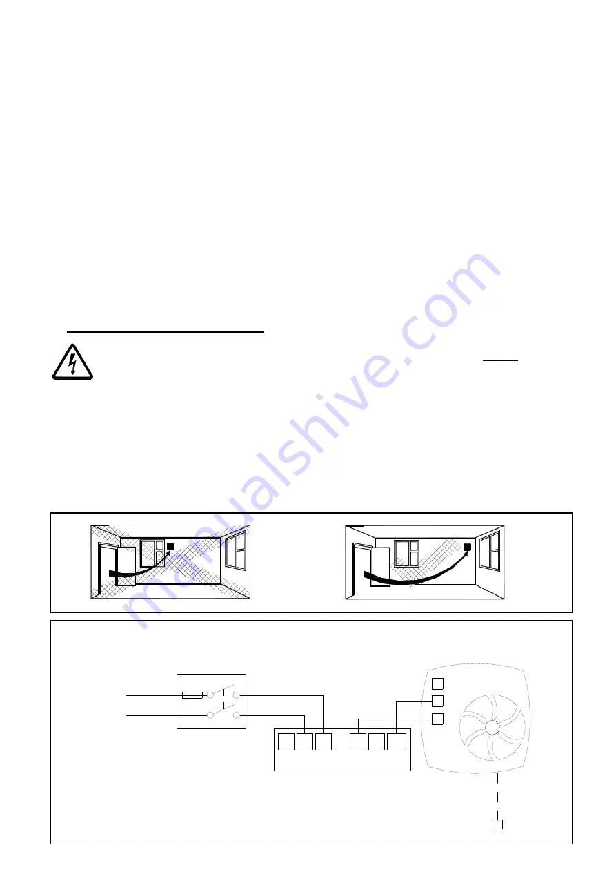


~

N

L

1 Phase Supply

(220-240V 50Hz).

FUSE

Switched

Fused Spur

(3A)

LS

12V

0V

Controller

Fan

12V D.C

SELV Supply

N

L

LS

LS

N

L

2

1

3


Fig.2 Continuous trickle (6l/s or 9l/s)  
with no remote boost facility 

Note:-

 (T, TP, HT & HTP – But TP & HTP can be boosted via pullcord)


Fig. 1 
Siting 
the 
fan. 


PULLCORD 

TP & HTP ONLY 

Summary of Contents for Centra Lo-Carbon SELV HT

Page 1: ...distat Timer HT 443177A Humidistat Timer Pullcord HTP 447128A Timer Pullcord TP PLEASE READ INSTRUCTIONS IN CONJUNCTION WITH ILLUSTRATIONS PLEASE SAVE THESE INSTRUCTIONS Centra Lo Carbon SELV IPX7 FAN...

Page 2: ...2...

Page 3: ...irect water spray for prolonged periods of time H Where ducted Fans are used to handle moisture laden air a condensation trap should be fitted Horizontal ducts should be arranged to slope slightly dow...

Page 4: ...hin reach of a person using a fixed bath or shower i e in a nearby wall However the fan must not be placed where it could be submerged in water or regularly exposed to direct water spray e g from a sh...

Page 5: ...the holes in the fan back plate Drill plug and screw into position 3 Fix exterior grille into position with the louvres positioned downwards Note The grille must comply with the standard requirements...

Page 6: ...y The fan has two boost speed settings for different installation requirements Max speed Dip switch 2 in the OFF position Fig 10 15l s speed Dip switch 2 should be in the ON position Factory set Fig 1...

Page 7: ...during the overrun time period the timer will reset the countdown timer back to the preset value There is no way of switching the fan back to trickle manually D SERVICING AND MAINTENANCE WARNING THE...

Page 8: ...g 5 Removing the grille for wiring and setting the controls 1 Loosen screw 2 Pull grille slightly away from bottom edge 3 Push grille upwards until clear from the fan chassis N L 1 Phase Supply 220 24...

Page 9: ...on 15l s speed boost Dip switch 2 should be in the ON position Fig 6 Accessing the control settings Fig 7 Removing the front grille panel for cleaning Dip switch Fig 8 Trickle speed selection and T HT...

Page 10: ...Notes...

Page 11: ...ogy Control Factor CTRL 0 95 0 65 0 65 0 95 Control Typology Clock Control Local Demand Control Local Demand Control Clock Control Declared Max Internal External Leakage Rates for BVUs or carry over f...

Page 12: ...ctive the product will be repaired or at the Company s option replaced without charge provided that the product Has been installed and used in accordance with the instructions given with each unit Has...

Reviews: