background image

Installation and wiring instructions for the Centrif Duo and Centrif Duo Plus extract fans. 


  IMPORTANT: 
  READ THESE INSTRUCTIONS 
  BEFORE COMMENCING THE  
  INSTALLATION 

 
DO NOT install this product in areas where the following may be present or occur: 


Excessive oil or a grease laden atmosphere. 


Corrosive or flammable gases, liquids or vapours. 

• 

Ambient temperatures higher than 40°C or less than –5°C. 

• 

Possible obstructions which would hinder the access or removal of the fan. 


SAFETY AND GUIDANCE NOTES 
A. 

All wiring to be in accordance with the current I.E.E. Regulations, or the appropriate standards 
of your country and 

MUST 

be installed by a suitably qualified person. 

B. 

The fan should be provided with a local isolator switch capable of disconnecting all poles, 
having a contact separation of at least 3mm. 

C. 

Ensure that the mains supply (voltage, frequency, and phase) complies with the rating label. 

D. 

The fan should only be used in conjunction with the appropriate Vent-Axia products. 

E. 

It is recommended that the connection to the fan connector terminals is made with flexible 
cable. 

F. 

When the fan is used to remove air from a room containing a fuel-burning appliance, ensure 
that the air replacement is adequate for both the fan and the fuel-burning appliance. 

G. 

Precautions must be taken to avoid the backflow of gases into the room from the open flue of 
gas or other fuel burning appliances 

H. 

The fan should not be used where it is liable to be subject to direct water spray for prolonged 
periods of time. 

I. 

Where ducted fans are used to handle moisture-laden air, a condensation trap should be 
fitted. Horizontal ducts should be arranged to slope slightly downwards away from the fan. 

J. 

This appliance is not intended for use by persons (including children) with reduced physical, 
sensory or mental capabilities, or lack of experience and knowledge, unless they have been 
given supervision or instruction concerning use of the appliance by a person responsible for 
their safety. 

K. 

Children should be supervised to ensure that they do not play with the appliance. 


DESCRIPTION 

As standard, the Centrif Duo and Centrif Duo Plus are suitable for panel/wall installations, surface 
mounting, either in a horizontal or vertical plane. A Flush Mount Kit (439256) is available as an 
accessory. Ø100mm ducting (flexible or rigid) can be attached providing rear exit as standard or 
side exit with the Flush Mount Kit. Adaptors for rectangular ducting can be used. For wall 
installations a Wall Kit (25 41 02 White / 25 41 00 Brown) can be used. Please see our catalogue 
or web site (www.vent-axia.com) for more information on ducting and termination options. 


A. INSTALLATION


A Backdraught Shutter Assembly is supplied. It is packed inside the product during transport. It is 
designed to block the duct when the fan is off in order to prevent cold draughts from outside 
entering the building. To use it, push it on to the end of the exhaust Spigot (

fig.1

) with the hinges 

on the flaps vertical. It is not required when the fan is set up to run continuously. 
 

Summary of Contents for Centrif Duo DP 25 63 20C

Page 1: ...ef N Centrif Duo P 25 61 20C Centrif Duo T 25 62 20C Centrif Duo DP 25 63 20C Centrif Duo HTP 25 64 20C Centrif Duo Plus P 43 16 13A Centrif Duo Plus T 43 16 14A Centrif Duo Plus DP 43 16 15A Centrif Duo Plus HTP 43 16 16A Centrif Duo Centrif Duo Plus Installation and Wiring Instructions Centrif Duo Plus Centrif Duo ...

Page 2: ...y Washable filter available separately for Centrif Duo Plus Pullcord Trickle speed LS connection to boost from a remote switch from off T DP HTP or trickle speed DP HTP only Two boost speed options available selectable during installation Adjustable timer overrun 1 30 mins approx Adjustable humidity sensor default 60 RH approx ...

Page 3: ... be used where it is liable to be subject to direct water spray for prolonged periods of time I Where ducted fans are used to handle moisture laden air a condensation trap should be fitted Horizontal ducts should be arranged to slope slightly downwards away from the fan J This appliance is not intended for use by persons including children with reduced physical sensory or mental capabilities or la...

Page 4: ...hat there is sufficient space for the product to be installed and that the Filter fig 3 can be removed for maintenance 3 Insert the wall sleeve with the larger diameter sleeve on the room side and cement the ends into position flush with the wall faces The wall sleeve should be angled downwards away from the fan to allow any condensation to drain to the outside 4 Outside Grille Using the Grille s ...

Page 5: ...STALLATION OR MAINTENANCE 1 OPERATION i As standard the HTP models will run continuously at trickle speed until either the pullcord LS or humidistat call for boost speed To disable the constant trickle option remove the cover over the PCB to the right of the impeller and remove the link wire between terminals 4 and 5 on the PCB fig 7 ii The pullcord on the DP models will cycle between off trickle ...

Page 6: ...ty adjuster fig 4 7 CLOCKWISE This makes the fan less sensitive to RH i e the fan will come on at a higher RH The fan will continue to run at boost after the RH has dropped below the set point for the time period set by the timer adjustment see 3 TIMER ADJUSTMENT above C WIRING WARNING THE FAN AND ANCILLARY CONTROL EQUIPMENT MUST BE ISOLATED FROM THE POWER SUPPLY DURING INSTALLATION OR MAINTENANCE...

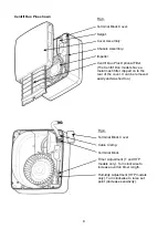
Page 7: ... lubrication Fig 1 Backdraught shutter assembly Flaps vertical Spigot Fig 2 Centrif Duo Plus Centrif Duo Cover Assembly Cover Screws Retaining edge for optional filter Centrif Duo Plus only Insert flat bladed screwdriver in here and pull Filter out to remove it ...

Page 8: ...f Duo models have a metal mesh filter clipped on to the rear of the cover It can be removed easily and washed too Fig 4 Terminal Block Cover Cable Clamp Terminal Block Timer Adjustment T and HTP models only Turn clockwise to increase overrun timer length Humidity Adjustment HTP models only Turn clockwise to raise set point decrease sensitivity ...

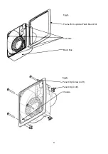
Page 9: ...9 Fig 5 Frame from optional Flush Mount Kit 4 screws Back Box Fig 6 Panel Clip Screw 4 off Panel Clip 4 off Chassis ...

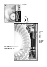
Page 10: ...10 Terminals Å1 Å2 Å3 Å4 Å5 See page 5 Section B Set Up Timer adjustment Humidity adjustment Fig 7 Setup HTP model shown PCBs may vary in look ...

Page 11: ...11 Fig 8 Siting of the fan 3 2 ...

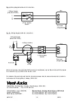
Page 12: ... Axia Ltd Fleming Way Crawley RH10 9YX abc Head Office Fleming Way Crawley West Sussex RH10 9YX Tel 01293 526062 Fax 01293 551188 UK NATIONAL CALL CENTRE Newton Road Crawley West Sussex RH10 9JA SALES ENQUIRIES Tel 0844 8560590 Fax 01293 565169 TECHNICAL SUPPORT Tel 0844 8560594 Fax 01293 532814 441678 F 0909 N L Ls 1 Phase Supply 220 240V 50 Hz 3A Fuse Pull Cord Lamp 3 Pole Isolator Switch Ceilin...

Reviews: