5
removed for maintenance.
IMPORTANT: Be careful to avoid joists and hidden pipes or
cables
.
3.
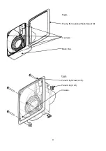
Remove the Back Box pieces by removing the four screws (
fig 5)
. Replace it with the Frame
from the Flush Mount Kit.
4.
Pass each of the long Panel Clip Screws
(fig.6)
supplied in the kit fully through the flange of
the Chassis and screw in to the four Panel Clips allowing enough space between the clip and
the flange for the thickness of the panel (so that the clips can spring open behind the panel).
5.
Set-up the appropriate speed selection and other features as outlined in
Section B SETUP.
6.
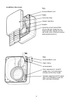
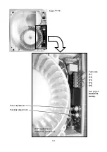
Remove the Terminal Block Cover in the top right corner (
fig 3
).
7.
Attach the ducting to the Spigot and locate the fan into the hole in the panel, ensuring the
cable is fed into the fan Chassis and the Panel Clips spring out behind the panel.
8.
Secure into position by carefully tightening the four Panel Clip Screws.
IMPORTANT: If
power tools are used, set them to the minimum torque setting or preferably use a
manual screwdriver. Do not over tighten.
9.
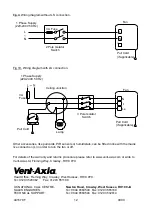
Select and follow the appropriate wiring diagram in
Section C WIRING.
10. Replace the Terminal Block Cover.
11. Ensure the Impeller rotates freely (
fig.3
).
12. Replace the Front Cover Assembly and tighten the two screws (
fig.
2).
13. Make sure that all covers are on correctly to ensure the optimum performance and water
ingress protection of the fan.
14. Switch the mains power supply on and check the fan is operating correctly.
B. SETUP
WARNING: THE FAN AND ANCILLARY CONTROL EQUIPMENT MUST BE
ISOLATED FROM THE POWER SUPPLY DURING INSTALLATION OR
MAINTENANCE.
1. OPERATION
i.
As standard, the
HTP models
will run continuously at trickle speed until either the
pullcord, LS or humidistat call for boost speed. To disable the constant trickle option,
remove the cover over the PCB to the right of the impeller, and remove the link wire
between terminals 4 and 5 on the PCB (
fig.7
)
.
ii.
The pullcord on the
DP models
will cycle between off, trickle and boost. The LS will switch
between boost and the previous state selected by the pullcord (either off, trickle or boost).
If you want to just use the LS to switch the DP model between trickle and boost, first set
the fan running to trickle speed with the pull cord, then remove the pull cord string.
iii. NOTE:
P and T models do not have a trickle speed
. These models can only switch from
off to the boost speed selected during setup (see 2. SELECTING THE BOOST SPEED).
iv.
To set the P model to run at boost speed constantly, (whenever power is connected to the
fan), set the pull cord to the on position and cut or remove the string. You will need to
replace the cover and turn the fan on to determine which is the on position of the pullcord.
v.
To set the T model to run at one of the boost speeds constantly, (whenever power is
connected to the fan), link the L & LS terminals of the mains terminal block together (
fig.4
).
2. SELECTING THE BOOST SPEED.
(See Technical Specifications on page 2).
This will determine the speed at which the fan will run when activated by either the pullcord, LS,
or relative humidity sensor depending on the fan model. The speed is factory set to kitchen.
For the T, HTP and DP models (NOT the P model):
i.
Link terminals 1 and 3 for Utility boost speed.
ii.
Or link terminals 2 and 3 for Kitchen boost speed.
IMPORTANT: Do not link across terminals 1 and 2.

