5
Connection of flexible connectors, transformation pieces, mounting feet, weather roof and discharge
cowl should be made using the 8 x M6 fixing points located on each side of the unit. Maximum thread
length into these fixing points is 12mm. Fixings are included with Vent-Axia supplied accessories.
Wiring
WARNING: THE FAN AND ANCILLARY CONTROL EQUIPMENT MUST BE ISOLATED
FROM THE POWER SUPPLY DURING THE INSTALLATION / OR MAINTENANCE.
EKF FANS ARE CLASS 1 AND MUST BE EARTHED.
1. Remove isolator cover & terminal box cover and put to one side.
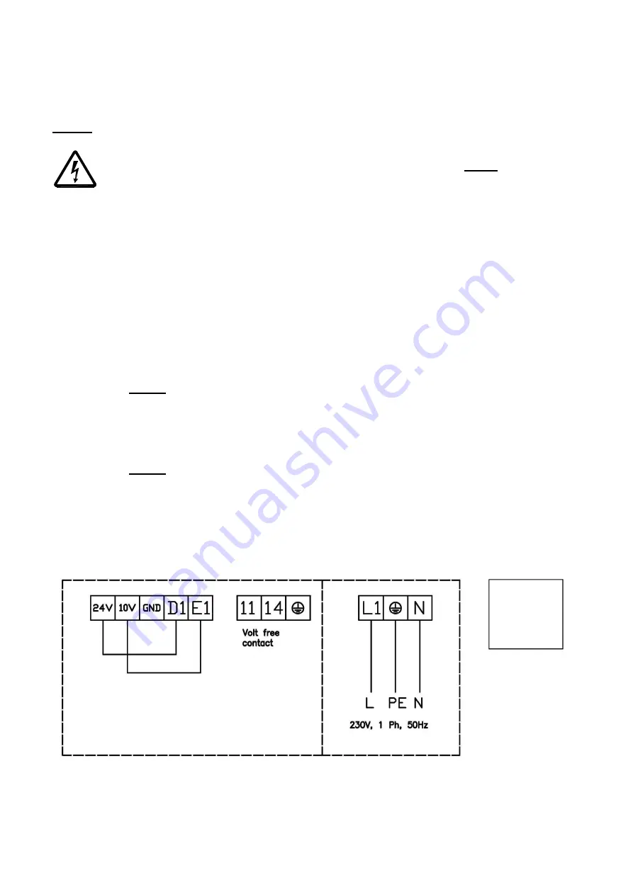
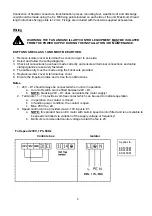
2. Select and follow the wiring diagrams.
3. Check all connections have been made correctly and ensure all terminal connections and cable
clamps/glands are securely fastened.
4. The cable entry must be made using the knockouts provided.
5. Replace isolator cover & terminal box cover.
6. Ensure the impeller rotates and is free from obstructions
Notes
1. 24V – D1 should always be connected when unit is in operation.
a. An on/off switch can be fitted between 24V – D1.
b.
NOTE:
breaking 24V – D1 does not isolate the motor supply!
2. Terminals 11 – 14 provide a volt-free contact which can be used to indicate operation.
a. In operation, the contact is closed.
b. In fault/no power condition, the contact is open.
c. Max. 250V ac, 2A.
3. Speed control can be provided via a 0-10V input to E1.
a.
NOTE:
this product has an EC motor with built-in speed control fitted and is not suitable to
be speed controlled via variation of the supply voltage or frequency!
b. Minimum recommended control voltage to start the fan is 2V.
Full speed 230V, 1Ph, 50Hz
Controls box
Isolator
Applies to:
EKF355E1
EKF400E1
EKF450E1


