3
Wiring diagram
Note:- 3 Phase fans
are fitted with a
flying lead.
EMF35532*/**
EMF40034*/**
EMF40032**/***
EMF45034*/**
EMF50034*/**
EMF56034**/***
EMF63034**/***
EMF71034**/***
Select the wiring diagram that relates to your fan
(Note:-
*/**/***
relates to fan control & protection, see back page for details.
C. MOTOR PROTECTION & CONTROL
*
May only be operated with frequency converter (max.230V)
**
Thermo contact must be connected to external tripping
unit. The internal thermal is not suitable to protect the motor
during a blockage. I.e. in cases where a motor blockage can
occur, a motor protection switch with corresponding rated
current should be prefixed. Ideally, we recommend to use a
protection switch with thermal and magnetic release.
***
For cost reasons, common frequency converters have no sinusoidal but a
pulse width signal at the outlet. This causes motor noise, which increases with
motor size. Depending on the ventilation design and the radiating surface the noise
is noticeable. At very low noise requirements this can be disturbing.
Under normal industrial applications, the noise is usually acceptable.
There are also frequency converters with sinusoidal output, but they are
significantly more expensive (coefficient 2..4). With these there is no
additional motor noise.
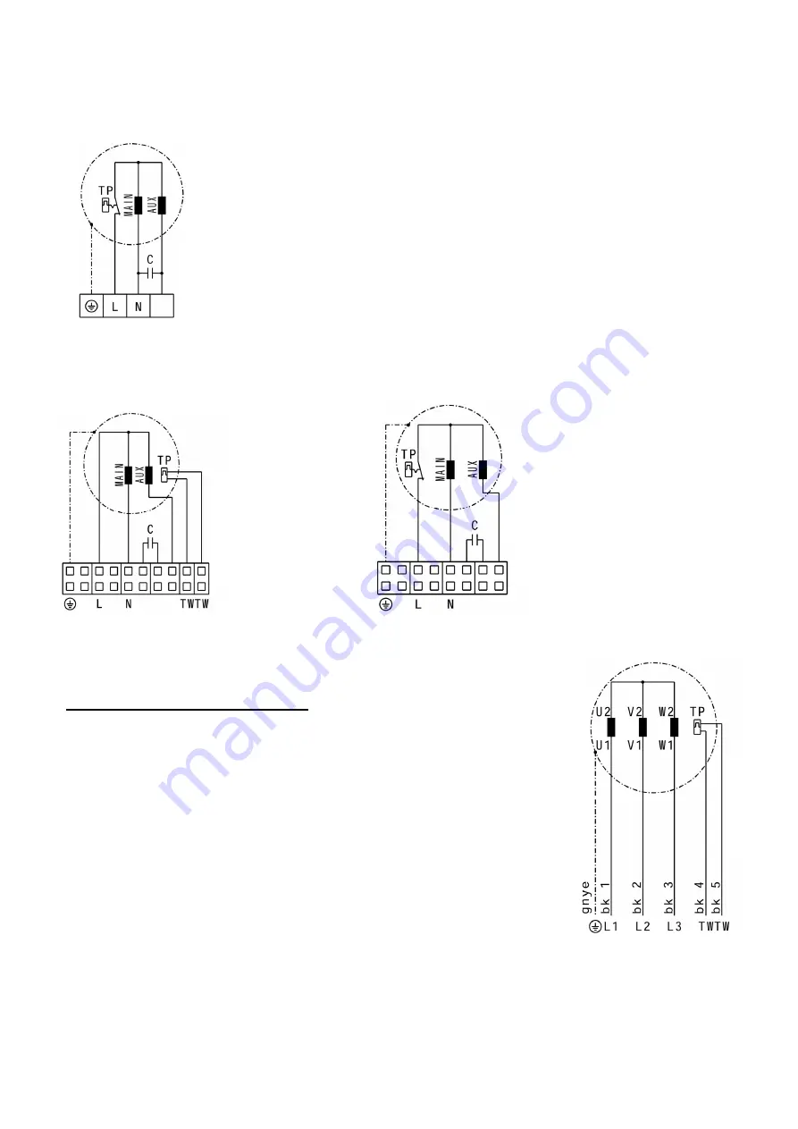
Wiring diagram
EMF35512**
EMF35514**
Wiring diagram
EMF45014**
EMF50014**
EMF56014**
EMF63014**
Wiring diagram
EMF40014


