Page 10
Specifications are subject to change without notice.
Installation Instructions
Distributed by Simx Limited
enquiry@manrose.co.nz | www.manrose.co.nz
Installation Instructions
Specifications are subject to change without notice.
Page 11
enquiry@manrose.co.nz | www.manrose.co.nz
Distributed by Simx Limited
MultiVent Continuous Extract Ventilation
MultiVent Continuous Extract Ventilation
Using instructions from the section “UNIT ADJUSTMENT” make the following changes:
LS1 change from Low to BOOST
D2 change from Purge to BOOST
With this completed the MultiVent once switched ON will operate in NORMAL speed (35%) when the bathroom FAN switch is turned on the
MultiVent will operate at BOOST (70%) speed clearing away steam and humidity if the kitchen FAN switch is turned on the MultiVent will operate
at BOOST (70%) if both bathroom and kitchen FAN switches are turned on together the MultiVent will operate at PURGE (100%) speed helping
to clear away steam and cooking odours. The toilet FAN switch will also turn the MultiVent on to BOOST (70%). Please note that only having the
2 larger rooms (bathroom and kitchen) switched on will activate PURGE (100%) speed.
FAULT CODES
If the MultiVent unit detects a fault it will display an error message on the HMI display.
Fault Code
Description
F01
Control fault – Unit failed startup check
F02
Motor Fault – No RPM
F03
Humidity/Temp sensor Fault – No value
F04
Temp or Humidity sensor connected via RF/RS485 is offline/Lost
COMMISSIONING – TYPICAL 3 ROOM SYSTEM
In the following step we will provide an example of how to wire and control an MultiVent system hardwired to a Bathroom, Kitchen and Toilet.
The MultiVent will utilize Humidity – Rapid Rise in its response and the 2 larger rooms (Bathroom and Kitchen) will also provide a PURGE speed
function if these 2 rooms are switched on together.
Before commencing please ensure that all power is OFF and ensure that it is electrically safe before starting.
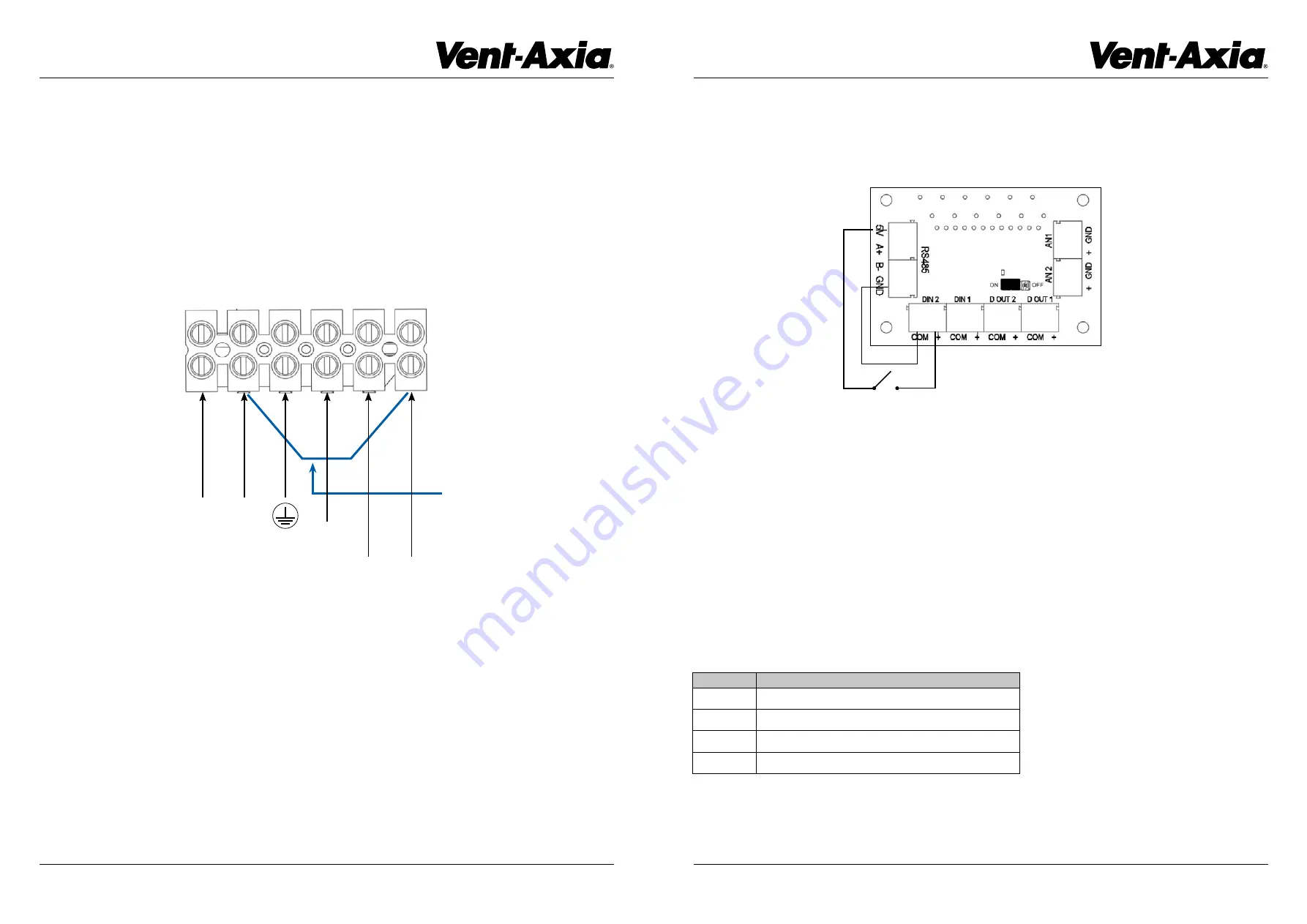
Wire the 230VAC connections as per the diagram below. Wire mains connections from a suitable source (lighting circuit) or add a new dedicated
circuit from an RCD protected 10A MCB with the cable to L (live - BROWN), N (neutral - BLUE) and E (protective earth – GREEN/YELLOW).
Wire a 230V connection from a switch located in the Bathroom that could be either a dedicated FAN switch (or a connection from a LIGHT switch)
and connect the L (BROWN) wire back to LS1. Do the same from a switch located in the Kitchen and connect the L (BROWN) wire back to LS2.
Hardwire a NEUTRAL LINK (BLUE or BLACK) from the N (neutral - BLUE) mains connection to the connection labelled NS (neutral switched).
L
N
E
LS1
LS2
NS
L
N
From
Bathroom
From
Kitchen
NS
NEUTRAL LINK
For the toilet the MultiVent will use its Extra Low Voltage connections for control. Using a short piece of wire connect a 0.5mm (or similar sized wire)
from the GND terminal at the RS485 connection to the COM terminal adjacent to DIN 2 (digital input 2) + connector. Using a twin red TPS cable
connect one RED core to the + connector at DIN 2 and connect the other RED core to the 5V terminal at the RS485 connection. Run the other end
of the cable to the toilet FAN switch and connect the 2 red cores to the C (common) and the normally open (usually labelled 1) connections at this
switch. See diagram below.
C
TOILET
1
RED
RED


