background image

10. This appliance is not intended for use by persons (including children) with 
reduced physical, sensory or mental capabilities, or lack of experience and 
knowledge, unless they have been given supervision or instruction concerning 
use of the appliance by a person responsible for their safety. 

11. Young children should be supervised to ensure that they do not play with 
the appliance. 

12. CAUTION: In order to avoid a hazard due to inadvertent resetting of the 
thermal cut-out, this appliance must not be supplied through an external 
switching device, such as a timer, or connected to a circuit that is regularly 
switched on and off by the utility. 

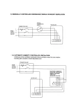
13. For 2 speed operation, Terminals L1 and L2 of the appliance must only be 
connected to the electrical supply through a changeover switch arrangement 
similar to that shown in wiring diagrams 5.3 or 5.4. Simultaneous connection of 
these terminals to the supply will energise both motor windings and cause the 
motor to overheat and cutout.


INSTALLATION GUIDANCE 

1. The installer is responsible for the installation and electrical connection of the system on site. It is the 
responsibility of the installer to ensure that the equipment is safely and securely installed and left only when 
mechanically and electrically safe. 

2. All regulations and requirements must be strictly followed to prevent hazards to life and property, both 
during and after installation, and during any subsequent servicing and maintenance. 

3. Certain applications may require the installation of sound attenuation to achieve the sound levels required.


4. The unit must not be connected directly to a tumble drier.


5. The supply air must be drawn from the exterior of the property.


6. The exhaust grille should be located at least 600mm away from any flue outlet. The inlet grille should  be 
located 2000mm away from any flue outlet. 


Disposal 

This product should not be disposed of with household waste. Please recycle where facilities exist. 
Check with your local authority for recycling advice


Summary of Contents for HR100S

Page 1: ...HR100S Heat Recovery Ventilation Unit Surface mounting two speed heat recovery extract and intake unit for bathrooms and toilets Installation and Maintenance Instructions Stock Ref No HR100S 141 10 010 ...

Page 2: ...ected and tested by a suitably qualified person after completion 3 Ensure the mains supply voltage frequency and phase complies with the rating label 4 The unit should be provided with a local double pole fused spur fitted with a 3A fuse having a contact separation of at least 3mm 5 These units must be earthed 6 Precautions must be taken to avoid the back flow of gases into the building from the o...

Page 3: ...pply will energise both motor windings and cause the motor to overheat and cutout INSTALLATION GUIDANCE 1 The installer is responsible for the installation and electrical connection of the system on site It is the responsibility of the installer to ensure that the equipment is safely and securely installed and left only when mechanically and electrically safe 2 All regulations and requirements mus...

Page 4: ... work out the cable runs When using surface wiring which is not contained in conduit the wiring must be securely anchored to the mounting surface Install the cable runs in conjunction with a fused and switched connection unit located in the vicinity of where the ventilation unit will be sited Ensure that the cables for the ventilation unit extend at least 400mm from the mounting surface FITTING IN...

Page 5: ... 2 Remove the terminal block cover after unscrewing the retaining screw 3 Remove the minimum amount of sheath and insulation from the supply cable and leads Slacken the cable clamps and feed the cable through the clamps Connect the conductors coloured red live L black neutral N and green yellow earth E to the appropriate terminals marked L1 L2 N and E of the terminal block in accordance with the w...

Page 6: ...he housing by grasping and gently but firmly pulling on its central vertical member 5 Wash the cover filter and heat exchanger in warm water using a mild detergent and subsequently dry them thoroughly Keep water away from all electrical components and wiring within the appliance 6 Replace the heat exchanger 7 Replace the filter in the cover 8 Refit the cover and tighten the four retaining screws 9...

Page 7: ......

Page 8: ......

Page 9: ......

Page 10: ......

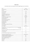
Page 11: ...3 h 0 56 Control Factor Control Typology CTRL Typology Control Factor CTRL 1 00 Control Typology Manual Control Declared Max Internal External Leakage Rates for BVUs or carry over for regenerative heat exchangers only Ext Leakage Rates for Ducted UVUs TBC Mixing Rate of Non Ducted BVUs not intended to be equipped with one duct connection on either supply or extract air side TBC Filter Warning RVU ...

Page 12: ...rating label attached to the unit Has not been subjected to misuse neglect or damage Has not been modified or repaired by any person not authorised by the company IF CLAIMING UNDER TERMS OF GUARANTEE Please return the complete product carriage paid to your original supplier or nearest Vent Axia Centre by post or personal visit Please ensure that it is adequately packed and accompanied by a letter ...

Reviews: