background image

3.0 Installation

7

3.3

Installing the Appliance

From inside

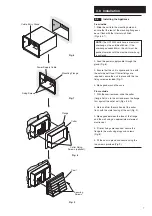
1. Slide the unit into the mounting hole and

ensure that the rear of the mounting flange can

be set flush with the internal wall finish 

(Figs. 6 & 7).

NOTE: 

The 

HR

100

W

 units have a maximum

overhang on the outside of 60mm. If the

overhang exceeds 60mm, the unit must be

pushed inwards until the maximum overhang

is achieved.

2. Feed the power supply cable through the

gland (Fig. 6).

3. Ensure that the unit is square and true with

the outside wall face. If firmer fixings are

required, secure the unit in place with the two

fixing screws provided (Fig. 7).

4. Make good around the case.

From outside

1. With the cowl removed, slide the collar

(flange first) on to the unit and press the flange

firm against the outer wall (Figs. 8 & 9).

2. Mark and trim the small end of the collar

flush with the metal casing of the unit (Fig. 9).

3. Make good between the face of the flange

and the wall using an appropriate waterproof

mastic seal.

4. If firmer fixings are required, secure the

flange to the wall using plugs and screws 

(Fig. 8).

5. Fit the cowl in place and secure using the

two screws provided (Fig. 9).

Fig. 6

Fig. 7

Fig. 8

Fig. 9

Cable Entry Gland

Fixing Screws

Mounting Flange

Power Supply Cable

Flange

Collar

Collar Fixing

Screws (optional)

Cowl

Securing

Screws

Summary of Contents for HR100W

Page 1: ...HR100W HR100WH HR30W Through The Wall Heat Recovery Ventilators Installation and Servicing Instructions Please leave these instructions with the user...

Page 2: ...spur fitted with a 3A fuse having a contact separation of at least 3mm 5 These units must be earthed 6 Precautions must be taken to avoid the back flow of gases into the building from the open flue o...

Page 3: ...rictly followed to prevent hazards to life and property both during and after installation and during any subsequent servicing and maintenance 3 Certain applications may require the installation of so...

Page 4: ...3 1 0 Introduction 4 2 0 Site Requirements 5 3 0 Installation 6 4 0 Electrical 8 5 0 Maintenance 9 6 0 Additional Information 1 7 0 Fixing Template 1 Section Page Contents T O P...

Page 5: ...extract air while transferring heat from the stale exhaust airflow to the fresh intake airflow This provides up to 70 heat recovery from the stale extracted air A boost speed facility is available for...

Page 6: ...icinity of excessive levels of airborne oil or grease 8 If the unit is installed in a room containing a fuel burning appliance the installer must ensure that air replacement is adequate for both appli...

Page 7: ...age 5 select a suitable site for the unit and controllers and work out the cable runs WARNING Before deciding on the final position for the unit check there are no buried cables pipes or obstructions...

Page 8: ...he unit in place with the two fixing screws provided Fig 7 4 Make good around the case From outside 1 With the cowl removed slide the collar flange first on to the unit and press the flange firm again...

Page 9: ...to the front of the unit and secure with the two screws provided Fig 11 8 Switch on the mains electrical supply and check the operation of the unit Fig 10 T O P Fig 11 Terminal Block Cover Heat Excha...

Page 10: ...Fig 12 5 Pull the four tubular inserts out of the rear of the grille and remove the filter Fig 13 6 Slide out the heat exchanger Fig 14 7 Wash the grille filter and heat exchanger in warm water using...

Page 11: ...months Clean cell replace filters the new filters will be supplied with 4 additional Timestrip indicators Note The above is the minimum requirement more frequent cleaning intervals may be needed depe...

Page 12: ...tomatically switch to BOOST speed at approximately 70 Relative Humidity at 20 C 3 To adjust this setting remove the grille and slide out the heat exchanger see page 9 4 The adjustment spindle is posit...

Page 13: ...12 HR100W HR100WH HR30W Template This Way Up 240mm 160mm Set this line true with spirit level 125mm minimum distance from ceiling 500mm minimum distance from floor Cable Entry...

Page 14: ...NOTES 13...

Page 15: ...NOTES 14...

Page 16: ...A Division of Vent Axia Limited Fleming Way Crawley West Sussex RH10 9YX Technical support 01293 526062 Fax 01293 539209 Internet site at www vent axia com 0918 370662 D...

Reviews: