4.0 Electrical
8
4.1
Electrical Connections
230V 50Hz 12W (normal) 31W (boost)
1. The
HR
100
W
is supplied with an in-built two
speed motor fitted.
2. Wiring must be via a 3A fused switched spur
with a 3mm contact separation in each pole.
The wiring should be suitably (Basec or Har)
approved cable of appropriate current carrying
capacity.
3. Ensure that the mains power supply is
isolated prior to installation.
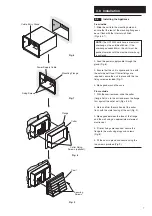
4. Remove the terminal block cover (Fig. 10)
and connect incoming wires to the appropriate
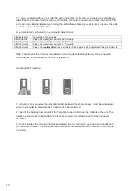
terminals, see relevant wiring diagram
(for
HR
100
WH
see page 11).
5. Replace th
e terminal block cover and
tighten
the cable gland (Fig. 10).
6. Slide the heat exchanger into the unit,
ensuring the ‘Top’ label is facing the front and
pointing upwards (Fig. 11).
7. Locate the grille on to the front of the unit
and secure with the two screws provided
(Fig. 11).
8. Switch on the mains electrical supply and
check the operation of the unit.
Fig. 10
T
O
P
Fig. 11
Terminal Block
Cover
Heat Exchanger
Securing Screws
Grille
HR
100
W
Terminals
3 amp fused supply
L
L
N
Neutral
Live
Earth
1
2
HR
100
W
Terminals
3 amp fused supply
NBSW/PCSW
L
L
N
Neutral
Live
Earth
1
2
HR
100
W
/
HR
100
W
H
Terminals
3 amp fused
supply
L
L
N
Neutral
Live
Switched Live
Light
Earth
1
2
1
2
3
L
N
HR
100
W
Terminals
VCON100 Terminals
3 amp fused supply
L
L
N
Neutral
Live
Earth
1
2
HR
100
W
Terminals
3 amp fused supply
L
L
N
Neutral
Live
Earth
1
2
HR
100
W
,
HR
30
W
and
HR
100
W
H units must not be wired in
conjunction with a light switch, units will fail.
HR
100
W
continuous normal speed.
HR
100
W
wiring to NBSW/PCSW switches for
manual, normal and boost switching.
HR
100
W
wiring to VCON100 controller for manual,
on/off, normal and boost switching.
HR
100
W
continuous boost speed.
Cable Entry Gland
Summary of Contents for HR100W
Page 14: ...NOTES 13...
Page 15: ...NOTES 14...


