background image

11

5.0 Installation Requirements

5.1

Location

1. The cooker hood MVHR unit is only suitable

for installation above a domestic cooker or

domestic hob. The HR205 must be sited a

minimum of 700 mm above the cooker/hob.

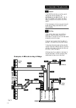
2. The exhaust duct must pass through an

outside wall or roof and discharge to atmosphere

in a suitable position .The clean air inlet duct

must pass through an outside wall or roof and be

suitably positioned to provide an adequate fresh

air supply from atmosphere.

5.2

Site requirements

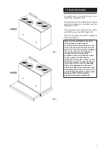
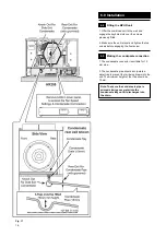
1. For the HR205 a flat vertical area 1332mm

high x 600mm wide is required for installation.

For the HR204 a flat vertical area 692mm high x

562mm wide is required for installation.

Important: The HR204 is not suitable for

installation above any cooking appliance

or with any extraction system servicing

a cooking appliance.

2. Before installation consideration must be

given to the position of the ductwork

connections, the electrical connection and the

condensate pipe connection.

Warning: Please check the information on

the data plate is compatible with local

supply conditions.

3. The installation must be carried out by a

competent person and be in accordance with the

relevant Building regulations (Scotland)

(consolidation), the Local building regulations,

the current I.E.E. Wiring regulations.

Reference should also be made to the BRE

digest 398 and CIBSE guidelines.

Warning: The addition of anything that

may interfere with the normal operation of

the appliance without the express written

permission of Vent-Axia Ltd could

invalidate the appliance warranty and

infringe regulations.

Warning: If the unit is fitted in a room

containing a bath or shower then

reference should be made to the current

I.E.E. Wiring Regulations and Building

Regulations.

Summary of Contents for HR205

Page 1: ...Please leave these instructions with the user Whole House Ventilation System with Heat Recovery and Cooker Hood HR205 User Installation Servicing Instructions...

Page 2: ...ayout 3 0 Technical Data 4 0 Appliance Operation 5 0 Installation Requirements 6 0 Installation 7 0 Wiring Diagrams 8 0 Commissioning 9 0 Maintenance 10 0 Changing Components 11 0 Fault Finding 12 0 S...

Page 3: ...e considered before siting the extract and inlet vents the vents must also be sited away from other flue terminals ventilators etc on the outside of the dwelling In addition there shall be adequate ve...

Page 4: ...ical ventilation with heat recovery MVHR unit designed solely to operate with the Vent Axia telescopic cooker hood The unit provides continuous extraction of stale air from the dwelling typically from...

Page 5: ...after thoroughly drying 1 2 Air Inlet Filter HR204 HR205 Fig 4 1 Lift off the front door panel by releasing the two hand screws and lifting upwards 2 Remove the air inlet filter by pulling forwards 3...

Page 6: ...or RH 4 Electrical Control Transformer 5 Fuse 3 15amp fast blow 6 Terminal Block 7 Overheat Sensor 8 Lower Fixing Hole 9 Fire Damper 10 Condensate Drain 15mm 11 Condensate Tray 12 Alternative outlet f...

Page 7: ...RH 4 Electrical Control Transformer 5 Fuse 3 15amp fast blow 6 Terminal Block 7 Lower Fixing Hole 8 Alternative outlet for condensate bottom 9 Condensate Drain 15mm 10 Condensate Tray 11 Alternative...

Page 8: ...weight kg 20 6 16 7 Voltage tappings Power consumption watts Power consumption watts Lights off Lights on 80 16 96 16 100 27 107 27 120 40 120 40 140 52 132 52 160 65 145 65 230 111 191 111 Duct conne...

Page 9: ...t gives the ventilation rates at each fan speed setting compared to the pressure drop of the system 0 50 100 150 300 350 250 200 0 20 10 30 50 70 40 60 80 90 100 110 120 130 140 150 160 170 180 190 20...

Page 10: ...trip in the fan senses temperature rise and breaks the electrical supply to the motor This can only be reset by disconnecting from the mains supply If the overheat thermostat senses an elevated rise...

Page 11: ...y extraction system servicing a cooking appliance 2 Before installation consideration must be given to the position of the ductwork connections the electrical connection and the condensate pipe connec...

Page 12: ...house 2 The duct work system should be sized and installed to minimise the pressure loss along it 3 Using larger diameter pipes and keeping the number of bends and fittings used to a minimum will redu...

Page 13: ...70495 is available for manual boost control remote from the unit An optional pull cord boost switch PCSW Part No 370278 is available for manual boost control remote from the unit 5 6 Electrical supply...

Page 14: ...um Top Clearance for servicing 200 Minimum Side Clearance 5 Minimum Side Clearance 5 Clearances HR204 Minimum Bottom Clearance 100 Minimum Front Clearance for servicing 250 280 Clearances HR205c Minim...

Page 15: ...ket in the protective box taking care to route the cables as shown Fig 16 Clip the box together and secure using the screws provided Locate the large cable grommet in the hole and ensure it is seated...

Page 16: ...s before engaging the final screw 6 5 Making the condensate connection 1 The condensate connector is suitable for 15 mm pipe 2 The condensate pipe should incorporate a water trap to prevent foul air b...

Page 17: ...the electrical connection Warning This appliance must be earthed 1 The normal running speed of the fans is set at 120v 2 The unit must be set to the appropriate voltage as determined by air flow requ...

Page 18: ...gr gr gr gr w w br br w br br Brown g y Green Yellow p Purple bk Black Key Colors b Blue gr Grey r Red w White L N L L N N Fuse 3 15AT Fan air in r r r r b b g y g y g y b gr gr br br c boost speed 2...

Page 19: ...Blue gr Grey r Red w White L N L N Fuse 3 15AT Fan air in r r r r b b g y g y g y Mains In 230v g y br b g y br b b b b br br b b b 1 2 3 4 Remove Link To Cooker Hood Earth for Inspection Panel Fan ai...

Page 20: ...nal Controls Fan air out Controller L N 160 140 120 100 80 O B C br br br Brown g y Green Yellow p Purple bk Black Key Colors b Blue gr Grey r Red w White L N L L N N Fuse 3 15AT Fan air in r r r r b...

Page 21: ...3 15AT Fan air in r r r r b b g y g y g y Mains In 230v g y br b g y br b b b b br br b b b 1 2 3 4 Earth for Inspection Panel Fan air out Controller L N 160 140 120 100 80 O B C br Brown g y Green Ye...

Page 22: ...eed 4 Pull the telescopic hood forward The unit will now switch to boost speed 5 Check the operation of the cooker hood lights 8 1a Prepare for commissioning HR204 1 Refit the front door panel by hook...

Page 23: ...from the appliance 7 Check the flow rate and adjust if necessary the remaining inlet valves 8 Repeat the checks and adjust until the system is correctly balanced Note If the flow rates have been achi...

Page 24: ...red Check the fire damper is in satisfactory condition and unaffected by debris and fat deposits Replace if necessary 7 Check both fans fan compartments and exhaust duct outlets for deposits Clean as...

Page 25: ...pliance will run on normal setting Extend the hood and the appliance will switch to boost setting With the appliance on boost check the operation of the cooker lights 14 Check the condition of the duc...

Page 26: ...Lift off the front door panel by releasing the two hand screws and lifting upwards 2 Remove the bottom electrical cover by releasing the 3 screws pulling the panel forwards and disconnecting the earth...

Page 27: ...te and lift to remove 3 Release the clip on the plastic plug and disconnect the plug 4 Slacken the two rear fan bracket screws 5 Remove the two front fan bracket screws and remove the fan assembly 6 D...

Page 28: ...the heat exchanger forwards and remove 3 Remove the four heat exchanger seals taking care to remove all the old adhesive backing 4 Fit the new seals ensuring they make good contact with the location...

Page 29: ...29 This page is intentionally blank...

Page 30: ...nough for any fault to become apparent 1 2 3 4 5 6 Controller Connector Block C Hood Plug Fan Plug D E 3 2 1 G F B A C 1 2 1 2 1 2 3 O B C L N Fuse 3 15AT WHC0035A Ensure the Cooker Hood is closed Ens...

Page 31: ...adjusted correctly Is there adequate airflow at the appliance inlets and outlets YES YES NO Ensure continuity across cooker hood plug and lead Replace cooker hood Replace bulbs Max 40 watts Replace bu...

Page 32: ...ault on wiring to external control Check external control rectify or replace as necessary NO Do the external controls have a mains supply from F2 reduced voltage supply from F1 Are both fans operating...

Page 33: ...t system and terminals for blockages or damage Ensure terminals are adjusted correctly Is there adequate airflow at the appliance inlets and outlets Replace bulbs Max 40 watts Unit operating satisfact...

Page 34: ...fan connector G2 G3 Is the capacitor reading approximately 2 F NO NO Has the fan thermostat trip operated see note 1 Fan has overheated Investigate the cause and rectify Replace fan section 10 3 NO Re...

Page 35: ...filter 7 372736 Heat exchanger 8 372737 Heat exchanger seals 4 off 9 372739 Outer door assembly 10 372741 Cooker hood seal 11 372743 Cooker hood filters set of two 12 372748 M5 wing screw 13 372777 L...

Page 36: ...372705C 0208...

Reviews: