32
11.0 Fault Finding
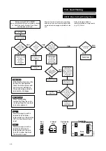
HR204 - Main Unit Fault Finding Chart
START
YES
NO
1
2
3
4
5
6
Controller
Connector
Block
Fan
Plug
D
3
2
1
G
F
B
A
C
1
2
1
2
1
2
3
O
B
C
L
N
Fuse
(3.15AT)
WHC0037A
Ensure continuity
between terminals
D5 & A1
and between
D6 & A2
Check mains
supply.
Is there
mains voltage
across terminals
A1/A2?
YES
NO
Investigate cause
and
rectify fault
Is the
fuse on the
controller
O.K.
YES
NO
Disconnect wires
from terminals
F1, F2 & F3.
Ensure voltage
selector wire is
correctly engaged.
Replace controller
Is the
voltage across
terminals B1 &
B2 between 80v
& 160v?
NO
Is the voltage
across F1 & B2
between 80v
& 160v?
Replace controller
NO
Is there mains
voltage between
F2 and B2
YES
NO
See Fan Fault
Finding Chart
Check external
control wiring.
Refer to 204 wiring
diagram (section 7)
Reconnect wires
to terminals
F1, F2 & F3.
Rectify fault
on wiring to
external control
Check
external
control,
rectify or
replace
as
necessary.
NO
Do the
external controls
have a mains supply
from F2 & reduced
voltage supply
from F1
Are both fans
operating?
YES
YES
YES
L
N
160
Voltage Selector Wire
140
120
100
80
Replace fuse
3.15AT
Before starting FAULT FINDING
carry out preliminary electrical systems checks
i.e. Earth Continuity, Polarity, Short Circuit
and Resistance to Earth.
Ensure all external controls are operating
and are set to normal running. Ensure that
a mains electrical supply is available to the
unit.
Refer to diagrams below to
identify terminals on components
(e.g. A1, D3 etc).
Note 1
Electricity supply must be
isolated and Fan Motor
temperature must be less than
100˚ to allow thermal trip to
reset.
WARNING
If the Fan thermal trip
has operated, check the
entire system and unit
for correct installation.
Check all ducting outside &
terminals for blockages.
IMPORTANT
When investigating
overheating allow the unit to
run long enough for any fault
to become apparent.
Summary of Contents for HR205
Page 29: ...29 This page is intentionally blank...
Page 36: ...372705C 0208...


