3.0 Installation
CG
-1
-1
/0
1
3.1
Controllers
1. The HR300 unit can be installed in conjunction
with a number of controllers.
VCON6(370356):
The VCON6 controller can be
used to provide Off/Low/Normal/Boost/Sensor
control. (The HS6 humidistat or TIM2 over-run
timer can be used in conjunction with the VCON6
controller to provide automatic control.
150VA (
563538):
The 150VA transformer,
when used with a trickle/boost switch (455213),
allows for a trickle and boost speed to be
selected. Only terminals providing 140V or
higher should be used as the unit will not
operate reliably bellow 140V.
Ecotronic 1.5A controller (W300310):
Provides variable speed control and on off and
auto (sensor) modes.
TIM2(370346):
The TIM2 is an overrun timer
which can also be used to control the HR200
unit via a remote sensor e.g. Humidity Sensor.
3.2
Initial Preparation
1. Select an approved electrical control
arrangement for the HR300 unit (above).
2. After considering the site requirements
(Section 2.0), select a suitable site for the unit
and controllers and work out the cable runs.
WARNING:
Before deciding on the final position
for the unit, check there are no buried cables,
pipes or obstructions on the outside wall.
Cable requirements:
Suitably (Basec or Har)
approved four core cable of appropriate current
carrying capacity.
3. Install the cable runs and appropriate
controllers in conjunction with a fused connection
unit. Contact gap must not be less than 3mm.
4. Working from the inside, mark out the
position of the mounting hole - 280mm wide x
380mm high (see Fixing Template).
5. Carefully cut the holes in the inner and outer
brick courses to form a suitable aperture to
receive the unit. Ensure that this is level.
NOTE:
Bricks will cut more easily and
accurately if a series of holes are drilled close
together along the marked lines.
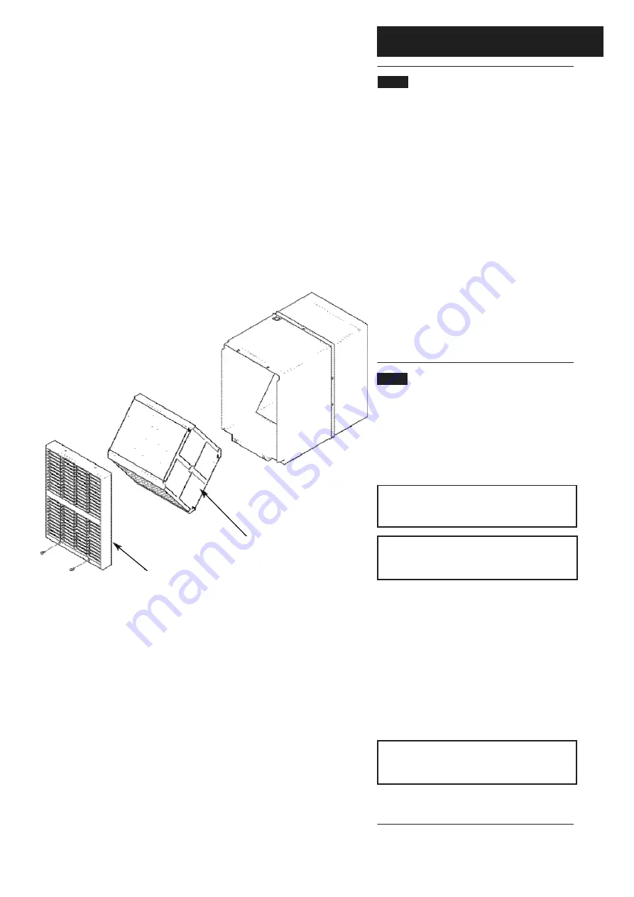
6. Remove the grille, heat exchanger, from the
unit (Fig. 3).
Heat Exchanger
Grille
Fig.3.


