background image

3.0 Installation

15

3.2

Installing the Ducting System 

(cont)

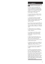
42. Rectangular ducting can be concealed in a

suspended ceiling having a minimum clearance

of 76mm (double battening) between the ceiling

and the plasterboard. This allows the use of

ceiling mounted supply (SV100) and extract

(EV100) valves utilising the 90° rectangular to

circular elbow joint (RD040). The spigot of the

RD040 may have to be trimmed to facilitate this.

43. The system can be used with a variety of

wall louvres, grilles and terminals. The RD501 is

an internal brick sized grille in white, 200mm x

55mm, and can be used in conjunction with an

adaptor (RD077) to convert to 110mm x 54mm.

This permits connection to rectangular ducting.

The RD501 grille can be used directly onto the

rectangular ducting either on the 54mm side or

the 110mm. This is done by cutting a hole,

50mm x 100mm, in the duct, cutting off the

sleeve at the rear of the RD501 to leave the

grille which can then be attached to the hole in

the duct by solvent or by a white silicon sealant.

44. Wall louvres such as the RD104 and the

ESG100 can also be used by converting to

circular with either a straight adaptor (RD070) or

a bent adaptor (RD040). It is important to

remember that the spigot on the RD104 is

concentric, which is difficult to use if the

rectangular ducting is hard against the ceiling or

wall or both. In this use an ESG100 which has

an eccentric spigot.

45. Squareduct 100 is designed to provide a

smooth bore ducting system which can be

surface mounted in areas where concealment or

boxing-in is difficult or undesirable. The ducting

(SD3) comes in 3m lengths or (SD1.5) in 1.5m

lengths and with clean butt joints and concealed

fixing, Squareduct can be fitted along the top of

a wall providing a clean edge between wall and

ceiling.

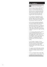
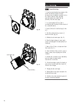
46. All fittings are supplied with a matching push

fit grommet (PDPLUG) on one side. This is

removable to allow the fitting to be drilled and

screwed through the hidden duct wall to either

ceiling or wall. Removal of the grommet provides

a 25mm diameter hole for access. This

procedure is very similar to that used for

rectangular ducting. After fixing, the 25mm dia

hole is then sealed using the grommet

(PDPLUG) (Fig. 15).

Push Fit Grommet

Fig. 15

Summary of Contents for HR320

Page 1: ...HR320 HR400 Whole House Ventilation System With Heat Recovery Installation and Servicing Instructions Please leave these instructions with the user HR400 HR320...

Page 2: ...2...

Page 3: ...3 1 0 Introduction 4 2 0 Site Requirements 5 3 0 Installation 7 4 0 Electrical 17 5 0 Commissioning 18 6 0 Servicing 20 7 0 Fault Finding 21 8 0 Guarantee 22 Section Page Contents...

Page 4: ...ally using a remote humidity sensor Trickle is continuous low speed at which the air in the property is changed approximately once every two hours Boost increases the ventilation rate throughout the p...

Page 5: ...capacity 4 The fan unit is Class 1 and must therefore be earthed 5 The fan unit must be connected to a trapped drainage system to allow condensate to be freely drained from the unit to the chosen dis...

Page 6: ...r servicing 12 Ensure that the mains electrical supply is switched off before commencing installation maintenance or servicing 13 Fire compartmentation must be maintained to comply with the requiremen...

Page 7: ...ted to the unit as shown Fig 4 HR320 5 The unit is supplied with a 22mm diameter condensate drain fitting packed loose in the box The WH unit casing is moulded with two 22mm diameter drainage spigots...

Page 8: ...8 The platform should be constructed from 50mm x 100mm timber bearers with a 19mm block board deck 9 The platform should incline the unit to ensure a fall to the drain outlet An acoustic mat ACMW HOUS...

Page 9: ...move the unit and position the mounting channel on the line 15 Mark through the three holes and drill and plug them Fig 11 16 Secure the mounting channel to the wall using the screws provided Fig 11 1...

Page 10: ...usings are secured in position in advance of the plasterboard panels being fixed by obtaining a sheet of plasterboard of the type and thickness to be used Cut a square of the sheet to just span two jo...

Page 11: ...nces as indicated for gables 13 The Quicktube Rigid UPVC duct system permits fast easy assembly whilst ensuring pressure proof system sealing 14 The ducts are delivered in lengths of 3m and are easily...

Page 12: ...d of flame of Class 1 tested to BS476 Part 7 971 It should however be protected from open flames or sparks and stored apart from highly flammable materials 21 The material provides resistance to heat...

Page 13: ...electrical supply is switched off 30 Cut to length strip and connect suitable cables between the fan unit controller and control switch in accordance with the wiring arrangements 31 When using surface...

Page 14: ...ver through the 25mm hole fix the ducting with an appropriate size and length of screw through the pilot hole into the ceiling wall The 25mm dia hole is then sealed using an appropriate sized plug PDP...

Page 15: ...licon sealant 44 Wall louvres such as the RD104 and the ESG100 can also be used by converting to circular with either a straight adaptor RD070 or a bent adaptor RD040 It is important to remember that...

Page 16: ...ics to DIN4102 B1 49 A square to round adaptor AD100 allows for simple connection to the Quicktube QT3 system and the use of all ancillary equipment Wall louvres such as the RD104 and the ESG100 can b...

Page 17: ...Fused Spur Normal Boost Switch C N B L N L N O B To HRV Unit 0 2 1 N L HS6 VCON77 C VCON7 and NBSW VCON100 Manual Normal to Boost Speed Control Select appropriate VCON77 tapping for NORMAL speed sett...

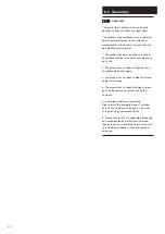
Page 18: ...lows 5 Check that there are air gaps under all internal doors to provide the transfer route of air from the living areas to the wet rooms Close all windows outside doors and all fresh air terminals in...

Page 19: ...al voltage setting by one step and to remeasure the individual air flow rates 12 When satisfied with all the extract air flow rates repeat the procedure stated above for all supply air terminals In th...

Page 20: ...r Fig 21 6 Wash the heat exchanger in warm water using a mild detergent and subsequently dry it thoroughly 7 Remove filter if fitted and replace with new filter media Fig 21 8 Clean the interior of th...

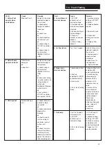
Page 21: ...failure 1 check airflow rate complies with commissioning data 2 modify ducting arrangement to relocate QTET a minimum of 2 5 diameters from air valve 3 switch off the mains electrical supply and remov...

Page 22: ...t 2 The product has not been connected to an unsuitable electricity supply 3 The product has not been subject to misuse neglect or damage 4 The product has not been modified or repair by any other per...

Page 23: ......

Page 24: ...VENT AXIA Ltd FLEMING WAY CRAWLEY WEST SUSSEX RH10 9YX www vent axia com Comp No 370712 Iss B 06 04...

Reviews: