3
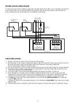
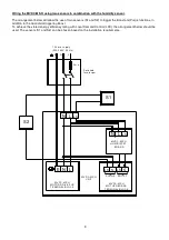
Installation and Wiring Instructions for the Multivent Multi-Speed Extract Fans.
IMPORTANT:
READ THESE INSTRUCTIONS BEFORE COMMENCING THE INSTALLATION
DO NOT install this product in areas where the following may be present or occur:
•
Excessive oil or a grease laden atmosphere.
•
Corrosive or flammable gases, liquids or vapours.
•
Ambient exhaust air temperatures higher than 40°C or less than –5°C.
•
Relative humidity above 90%
•
Possible obstructions which would hinder the access or removal of the Unit.
•
Sudden ductwork bends or transformations close to the Unit.
SAFETY AND GUIDANCE NOTES
1. DO NOT install this product in areas where the following may be present or occur:
1.1. Excessive oil or a grease laden atmosphere.
1.2. Corrosive or flammable gases, liquids or vapours.
1.3. Ambient temperatures higher than 40°C or less than -5°C.
1.4. Possible obstructions which would hinder access or removal of the Fan.
2. All wiring to be in accordance with the current I.E.E. Regulations, or the appropriate standards of your country and
MUST be installed by a suitably qualified person.
3. The fan should be provided with a 3A fused, isolator switch capable of disconnecting all poles, having a contact
separation of at least 3mm.
4. Ensure that the mains supply (voltage, frequency, and phase) complies with the fan’s rating label.
6. When the fan extracts air from a room containing an open flue of a gas or fuel burning appliance, precautions
must be taken to avoid the back-flow of gases into the room.
7. The fan should not be used where it is liable to be subjected to direct water spray.
8. The fan should be mounted at the highest point in the system to protect it from condensation build up.
9. This fan should be vented to the outdoors.
10. This appliance is not intended for use by persons (including children) with reduced physical, sensory or mental
capabilities, or lack of experience and knowledge, unless they have been given supervision or instruction concerning
use of the appliance by a person responsible for their safety.
11. Children should be supervised to ensure that they do not play with the appliance.
12. PLEASE NOTE: Some older fluorescent and low energy lighting products can interfere with other
electronic/timing circuits. For reliable operation of timers use post 2000 low energy bulbs or tungsten filament bulbs
in the room lighting circuit.
TYPICAL INSTALLATION
Summary of Contents for Lo-Carbon MULTIVENT MVDC-MS
Page 2: ...2...


