7
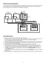
MVDC-MS (437634B) WIRING DIAGRAM
To achieve the stated energy efficiency rating with Local Demand Control (LDC), the unit should be used with two
sensor and be able to run on all three speeds. An example of how this can be achieved is shown below, the
sensors/switches can be chosen based on the installation requirements.
B. MVDC-MS H (443298A):
1. Remove the cover by undoing the four screws and lifting it away.
2. With the power off and using a suitable mains power cable from a switched, fused spur connect the Live and
Neutral to the power supply Terminal block and connect the Earth to the power supply PCB.
Use the cable clamps provided to secure the lead.
3. Ensure all connections have are correct and that all terminal screws and cable clamps are securely fastened.
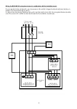
4. To enable the fan to switch to purge speed (maximum speed) connect the switched live connection to the
‘Purge’ LS connection on the mother board.
5. The output (230V) from the internal humidistat PCB is connected to the ‘Boost’ LS terminal.
6. Upon installation it is possible that the humidity controller will make the fan run continuously until it has
acclimatised to the environment. As part of the installation process it is important to set/adjust the humidity
sensitivity to the desired position. The controller is already factory set to switch on at about 70% R.H.
7. To
Lower
the set-point use the enclosed adjuster to turn the adjuster
ANTICLOCKWISE
. This makes the
controller
More
sensitive.
To Raise the set-point use the enclosed adjuster to
turn the adjuster
CLOCKWISE
. This makes the controller
Less
sensitive.
8. Following these set-up instructions, switch the mains supply on and check the system is operating correctly.
Fuse
L
N
E
1 Phase supply
(220-240V 50 Hz)
Switched
fused spur
MVDC-MS
MOTOR DRIVE PCB
TERMINAL BLOCK
E N L
Switch
(455213)
(Not supplied)
LS N LS N
MVDC-MS
MOTHERBOARD
TERMINAL BLOCK
PURGE
BOOST
MVDC-MS UNIT
Humidity Sensor
(563550)
(Not supplied)
Summary of Contents for Lo-Carbon MULTIVENT MVDC-MS
Page 2: ...2...


